Tag Archives: Cisco

vSONIC Virtual Switch on EVE-NG

SONiC is an open source network operating system based on Linux that runs on switches from multiple vendors and ASICs. SONiC offers a full-suite of network functionality, like BGP and OSPF, VXLAN that has been production-hardened in the data centers of some of the largest cloud-service providers.

The community around SONiC has been growing and includes Juniper including Apstra, Arista, Nokia, Alibaba, Comcast, Cisco, Broadcom, Nvidia-Mellanox and VMware. SONiC underpins Microsoft’s Azure networking services. According to IDC, a SONiC data-center switch market will be worth $2 billion by 2024.

Some term it as ‘Linux of Networking’.

In this blog, we will see how to spin up a sample topology using vSONIC Virtual Switch on EVE-NG.

To start with, we will use mssonic.yml file which lists the generic parameters for spinning up the instance.

  1. Copy mssonic.yml file into “/opt/unetlab/html/templates/intel” or “/opt/unetlab/html/templates/amd” based on your cpu. In my case, I am using EVE-NG on macbook so I have used Intel.

root@eve-ng:~# ls -l /opt/unetlab/html/templates/intel/ | grep mssonic

-rw-r–r– 1 root root 1993 Jul 30 22:41 mssonic.yml

root@eve-ng:~#

2. Create a folder under “opt/unetlab/addons/qemu/” with name “mssonic-version/” like “mssonic-3.1.2”.

Keyword “mssonic” is important as using this only, eve-ng will recognize this image.

root@eve-ng:~# ls -l /opt/unetlab/addons/qemu/ | grep ms

drwxr-xr-x 2 root root 4096 Jul 30 22:48 mssonic-3.1.2

root@eve-ng:~#

https://github.com/Broadcom/sonic-VirtualSwitch/tree/master/3.1.2

3. Gunzip the .gz file to extract the image file.

root@eve-ng:/opt/unetlab/addons/qemu/mssonic-3.1.2# gunzip sonic-vs-3.1.2.img.gz

root@eve-ng:/opt/unetlab/addons/qemu/mssonic-3.1.2# ls -l

total 2380932

-rw-r–r– 1 root root 2438070272 Jul 30 22:55 sonic-vs-3.1.2.img

4. Rename sonic-vs-3.1.2.img to virtioa.qcow2. Please make sure to rename only and don’t convert it.

root@eve-ng:/opt/unetlab/addons/qemu/mssonic-3.1.2# mv sonic-vs-3.1.2.img virtioa.qcow2

root@eve-ng:/opt/unetlab/addons/qemu/mssonic-3.1.2# ls -l

total 2380932

-rw-r–r– 1 root root 2438070272 Jul 30 22:58 virtioa.qcow2

5. Fix the permissions as usual on eve-ng.

root@eve-ng:/opt/unetlab/addons/qemu/mssonic-3.1.2# /opt/unetlab/wrappers/unl_wrapper -a fixpermissions

root@eve-ng:/opt/unetlab/addons/qemu/mssonic-3.1.2#

Now we all set to use this under EVE-NG

I have made a simple leaf-spine topology using Sonic Virtual Switches

6. Open the Eve-NG UI.

Add the new Node, and select Sonic Router as below.

7. Change any settings here if you need however defaults should be good.
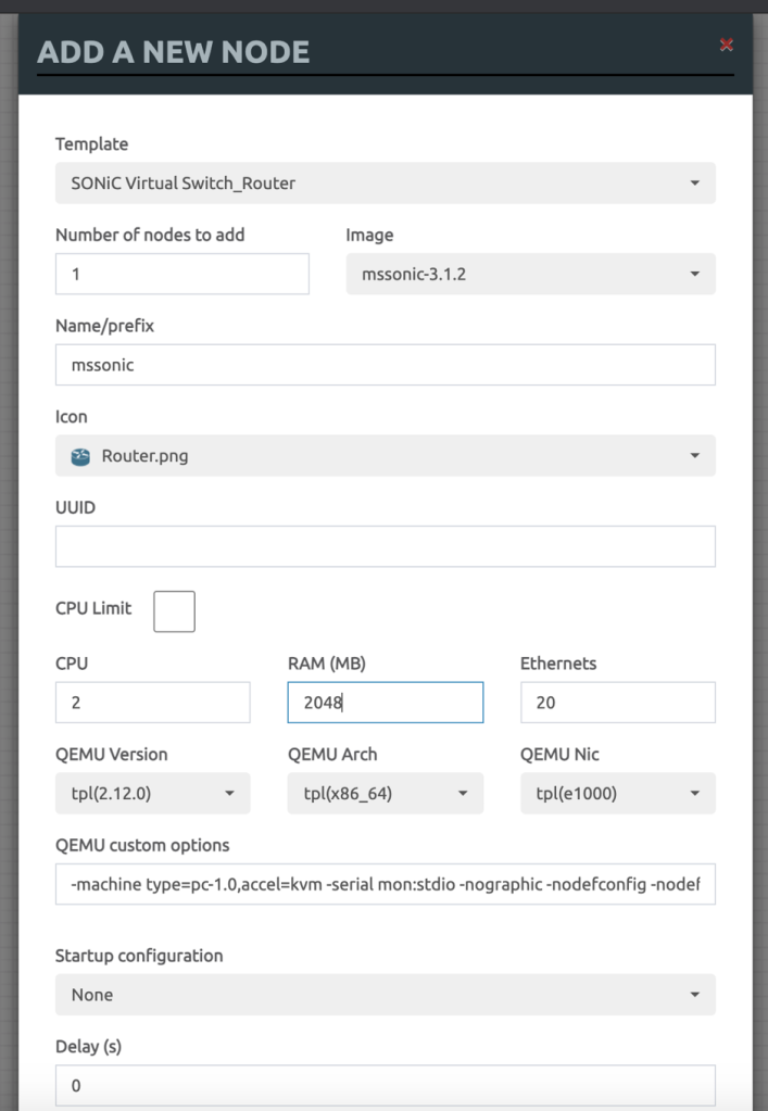
8. I have built a simple Leaf-Spine topology using 4 Sonic VS.

9. Start one or more Switches and let it boot.

Trying 172.16.137.130…

Connected to 172.16.137.130.

Escape character is ‘^]’.

Jul 31 15:30:59.295935 2021 sonic INFO sonic-ztp[3850]: ZTP service started.

Jul 31 15:30:59.295971 2021 sonic INFO sonic-ztp[3850]: Failed to set system MAC address as the random number generator seed input.

Jul 31 15:30:59.295999 2021 sonic INFO sonic-ztp[3850]: Checking running configuration to load ZTP configuration profile.

Jul 31 15:30:59.893505 2021 sonic INFO sonic-ztp[3845]: Waiting for system online status before continuing ZTP. (This may take 30–120 seconds).

Debian GNU/Linux 9 sonic ttyS0

Jul 31 15:31:34.932822 System is ready

Jul 31 15:31:36.290136 2021 sonic INFO sonic-ztp[3845]: System is ready to respond.

Jul 31 15:31:36.308466 2021 sonic INFO sonic-ztp[3850]: Link up detected for interface Ethernet0

Jul 31 15:31:36.308525 2021 sonic INFO sonic-ztp[3850]: Link up detected for interface Ethernet1

Jul 31 15:31:36.308554 2021 sonic INFO sonic-ztp[3850]: Link up detected for interface Ethernet2

Jul 31 15:31:36.308581 2021 sonic INFO sonic-ztp[3850]: Link up detected for interface Ethernet3

Jul 31 15:31:36.308609 2021 sonic INFO sonic-ztp[3850]: Link up detected for interface Ethernet4

Jul 31 15:31:36.308637 2021 sonic INFO sonic-ztp[3850]: Link up detected for interface Ethernet5

Jul 31 15:31:36.308664 2021 sonic INFO sonic-ztp[3850]: Link up detected for interface Ethernet6

Jul 31 15:31:36.308741 2021 sonic INFO sonic-ztp[3850]: Link up detected for interface Ethernet7

Jul 31 15:31:36.308769 2021 sonic INFO sonic-ztp[3850]: Link up detected for interface Ethernet8

Jul 31 15:31:36.308821 2021 sonic INFO sonic-ztp[3850]: Link up detected for interface Ethernet9

Jul 31 15:31:36.308850 2021 sonic INFO sonic-ztp[3850]: Link up detected for interface Ethernet10

Jul 31 15:31:36.309163 2021 sonic INFO sonic-ztp[3850]: Link up detected for interface Ethernet11

Jul 31 15:31:36.340452 2021 sonic INFO sonic-ztp[3850]: Link up detected for interface Ethernet12

Jul 31 15:31:36.340489 2021 sonic INFO sonic-ztp[3850]: Link up detected for interface Ethernet13

Jul 31 15:31:36.340761 2021 sonic INFO sonic-ztp[3850]: Link up detected for interface Ethernet14

Default username/pwd – admin/YourPaSsWoRd

10. Once up and running, you would see lots of ztp related messages which can be disabled using below command.

sudo config ztp disable

sudo config save -y

11. Once done, you can go into sonic cli, using sonic-cli

admin@sonic:~$ sonic-cli

sonic#

sonic#

sonic# ?

  clear        Clear commands

  configure    Enter configuration mode

  copy         Perform file copy operations

  exit         Exit from the CLI

  fast-reboot  fast-reboot [options] (-h shows help)

  image        Image related commands

  logger       Enter messages into the system log

  no           No commands under Exec mode

  ping         Send ICMP ECHO_REQUEST to network hosts

  ping6        Send ICMPv6 ECHO_REQUEST to network hosts

  reboot       reboot [options] (-h shows help)

  renew        Renew commands

  show         Show running system information

  terminal     Set terminal settings

  tpcm         SONiC image installation manager

  traceroute   Print the route packets take to the host

  traceroute6  Print the route packets take to the IPv6 host

  warm-reboot  warm-reboot [options] (-h shows help)

  write        Save config

sonic#

to prove its working, lets configure IP Addresses on Interfaces and see if we can ping each other.

On Leaf-1:

sonic(config)# hostname leaf-1

leaf-1#

leaf-1#

leaf-1#

leaf-1#

leaf-1# show running-configuration interface Ethernet 0

!

interface Ethernet0

 mtu 9100

 speed 25000

 fec none

 no shutdown

 ip address 10.10.10.2/30

leaf-1#

On Spine-1:

spine-1# show running-configuration interface Ethernet0

!

interface Ethernet0

 mtu 9100

 speed 25000

 fec none

 no shutdown

 ip address 10.10.10.1/30

spine-1#

12. Ping the other end to find everything is working

spine-1# ping 10.10.10.2

PING 10.10.10.2 (10.10.10.2) 56(84) bytes of data.

64 bytes from 10.10.10.2: icmp_seq=1 ttl=64 time=5.32 ms

64 bytes from 10.10.10.2: icmp_seq=2 ttl=64 time=1.34 ms

^C

— 10.10.10.2 ping statistics —

2 packets transmitted, 2 received, 0% packet loss, time 1001ms

rtt min/avg/max/mdev = 1.349/3.336/5.323/1.987 ms

spine-1#

That’s all, hope you like it.. In next sessions, we can go through some more specific scenarios around it.
Segment Routed L2VPN TE – Cisco IOS-XR

Hi All

Let’s see Segment routing in action in this blog particularly on IOS-XR. Segment routing is quite new concept which is picking pace these days. In my earlier blog I listed the differences between Segment routing and RSVP-TE and SR can replace it and there are certain areas where it may not be able to help however L3VPN and L2VPN Traffic Engineering is surely one area where it can be used and in this blog we will use SR as TE while configuring the L2VPN.

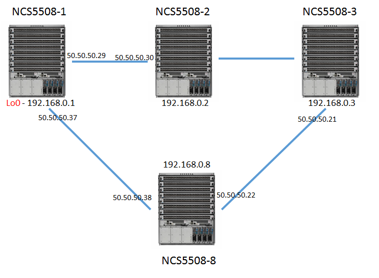
For this we will take NCS5508 as our router platform in below topology where we will configure the L2VPN SR-TE between NCS5508-1 to NCS5508-3 via NCS5508-8.

Segment Routing in IOS-XR


Let’s see the SR config first.

SR beauty is that there is no special protocol needed to run it. SR Labels will be advertised in OSPF/ISIS and these protocols have been uplifted to carry them. SR Labels are carried in Type 10 Opaque area LSA as TLV.

If you are familiar with OSPF config in IOS-XR, most of the config below looks similar to you as we have just enabled OSPF under area0 and added interfaces under it.

However there are 3 configs highlighted in RED which we have enabled for Segment routing.

RP/0/RP0/CPU0:ncs5508-1#show running-config router ospf
router ospf 1
 nsr
 distribute link-state
 segment-routing mpls
 nsf ietf
 segment-routing sr-prefer
 area 0
 mpls traffic-eng
 interface Loopback0
 passive enable
 prefix-sid index 1 explicit-null
 !
 interface HundredGigE0/1/0/0
 cost 1
 network point-to-point
 !
 interface FortyGigE0/2/0/8
 cost 4
 network point-to-point
 !
 interface FortyGigE0/2/0/10
 cost 4
 network point-to-point
 !
 interface FortyGigE0/2/0/18
 cost 4
 network point-to-point
 !
 !
 mpls traffic-eng router-id Loopback0
!

segment-routing mpls , this command causes OSPF to originate RI LSA, Extended Prefix and Extended Link LSAs. It enables MPLS on all interfaces in area(s) enabled for SR and programs SR MPLS labels for forwarding.

segment-routing sr-prefer is used to set the preference of segment routing (SR) labels over label distribution protocol (LDP) labels in case both are available towards destination in your network.

prefix-sid index 1 explicit-null — A prefix SID is associated with an IP prefix. The prefix SID is manually configured from the segment routing global block (SRGB) range of labels. The prefix segment steers the traffic along the shortest path to its destination. A node SID is a special type of prefix SID that identifies a specific node. It is configured under the loopback interface with the loopback address of the node as the prefix. The prefix SID is globally unique within the segment routing domain.

Let’s verify it

RP/0/RP0/CPU0:ncs5508-1#show ospf sid-database
SID Database for ospf 1 with ID 192.168.0.1

SID Prefix/Mask
-------- ------------------
1 192.168.0.1/32 (L)
2 192.168.0.2/32
3 192.168.0.3/32
4 192.168.0.4/32
5 192.168.0.5/32
6 192.168.0.6/32
7 192.168.0.7/32
8 192.168.0.8/32


In the same way we have configured the Node-SID as same index as last octet on lo0 interface.

RP/0/RP0/CPU0:ncs5508-1#show ospf database opaque-area 192.168.0.1/32
 OSPF Router with ID (192.168.0.1) (Process ID 1)
Type-10 Opaque Link Area Link States (Area 0)
LS age: 782
 Options: (No TOS-capability, DC)
 LS Type: Opaque Area Link
 Link State ID: 7.0.0.1
 Opaque Type: 7
 Opaque ID: 1
 Advertising Router: 192.168.0.1
 LS Seq Number: 800006fa
 Checksum: 0xed8b
 Length: 44
Extended Prefix TLV: Length: 20
 Route-type: 1
 AF : 0
 Flags : 0x40
 Prefix : 192.168.0.1/32
SID sub-TLV: Length: 8
 Flags : 0x50
 MTID : 0
 Algo : 0
 SID Index : 1
RP/0/RP0/CPU0:ncs5508-1#show mpls forwarding
Local  Outgoing    Prefix             Outgoing     Next Hop        Bytes
Label  Label       or ID              Interface                    Switched

—— ———– —————— ———— ————— ————

16002  Exp-Null-v4 SR Pfx (idx 2)     Hu0/1/0/0    50.50.50.30     0
16003  16003       SR Pfx (idx 3)     Hu0/1/0/0    50.50.50.30     0
16004  Exp-Null-v4 SR Pfx (idx 4)     Fo0/2/0/8    50.50.50.25     0
16005  16005       SR Pfx (idx 5)     Fo0/2/0/8    50.50.50.25     6421133
16006  16006       SR Pfx (idx 6)     Hu0/1/0/0    50.50.50.30     0
       16006       SR Pfx (idx 6)     Fo0/2/0/8    50.50.50.25     0
16007  16007       SR Pfx (idx 7)     Hu0/1/0/0    50.50.50.30     0
16008  Exp-Null-v4 SR Pfx (idx 8)     Fo0/2/0/18   50.50.50.38     0

Now let’s create a Segment routed TE EVPN based P2P L2 Circuit. 🙂

Ideally we know that Controller is needed to play with Segment routed labels and Controller can insert the appropriate labels required for TE however if you don’t have Controller, you can configure the path by explicitly giving the path through which traffic will be going.

So we will start with l2vpn xconnect taking edge interface on NCS5508-1 and assigning a EVPN EVI 1100 with source and target ac-id (attachment circuit id) and associate it with pw-class which we will define in next step.


RP/0/RP0/CPU0:ncs5508-1#show running-config l2vpn xconnect group evpn-vpws p2p vpws1
l2vpn
 xconnect group evpn-vpws
 p2p vpws1
 interface HundredGigE0/2/0/2.1100
 neighbor evpn evi 1100 target 11003 source 11001
 pw-class vpws1-class
 !
 !
 !
! 

Pw-class is associated with sr-te policy to steer traffic through the network. An SR-TE policy path is expressed as a list of segments that specifies the path, called a segment ID (SID) list. Each segment is an end-to-end path from the source to the destination, and instructs the routers in the network to follow the specified path instead of the shortest path calculated by the IGP

RP/0/RP0/CPU0:ncs5508-1#show running-config l2vpn pw-class vpws1-class
l2vpn
 pw-class vpws1-class
 encapsulation mpls
 preferred-path sr-te policy vpws1-policy
 !
 !
!
RP/0/RP0/CPU0:ncs5508-1#show running-config segment-routing traffic-eng policy vpws1-policy
segment-routing
 traffic-eng
 policy vpws1-policy
 color 10 end-point ipv4 192.168.0.3
 candidate-paths
 preference 200
 dynamic
 metric
 type te
 !
 !
 !
 preference 300
 explicit segment-list vpws1-path
 !
 !
 !
 !
 !
!

So in our policy, we have defined one preferred path which is dynamic and if that fails it should failover to explicitly configured segment list defined via path vpws1-path.

RP/0/RP0/CPU0:ncs5508-1#show running-config segment-routing traffic-eng segment-list vpws1-path
segment-routing
 traffic-eng
 segment-list vpws1-path
 index 10 address ipv4 50.50.50.38
 index 20 address ipv4 50.50.50.21
 !
 !
!

So if we see currently the route towards NCS5508-3, it’s going via IGP Route and not taking our defined list which is expected.

RP/0/RP0/CPU0:ncs5508-1#show route 192.168.0.3
Wed Jun 27 14:49:59.487 UTC
Routing entry for 192.168.0.3/32
 Known via "ospf 1", distance 110, metric 3, labeled SR, type intra area
 Installed Jun 27 14:47:18.930 for 00:02:40
 Routing Descriptor Blocks
 50.50.50.30, from 192.168.0.3, via HundredGigE0/1/0/0
 Route metric is 3
 No advertising protos.

So let’s see our L2VPN status.

RP/0/RP0/CPU0:ncs5508-1#show l2vpn xconnect group evpn-vpws detail
Group evpn-vpws, XC vpws1, state is up; Interworking none
 AC: HundredGigE0/2/0/2.1100, state is up
 Type VLAN; Num Ranges: 1
 Rewrite Tags: []
 VLAN ranges: [1100, 1100]
 MTU 9016; XC ID 0x1000001; interworking none
 Statistics:
 packets: received 157064234, sent 157063216
 bytes: received 234968088320, sent 234966565392
 drops: illegal VLAN 0, illegal length 0
 EVPN: neighbor 192.168.0.3, PW ID: evi 1100, ac-id 11003, state is up ( established )
 XC ID 0xc0000001
 Encapsulation MPLS
 Source address 192.168.0.1
 Encap type Ethernet, control word disabled
 Sequencing not set
 Preferred path Active : SR TE vpws1-policy, Statically configured, fallback enabled
 Tunnel : Up

 EVPN  Local Remote
 ------------ ------------------------------ -----------------------------
 Label 64007 64006
 MTU   9016  9016
 Control word disabled disabled
 AC ID 11001 11003
 EVPN type Ethernet Ethernet

So if we go n shut the primary dynamic path we can see the forwarding table moves over to our segment-list defined for label 16003 which is for NCS5508-3.

RP/0/RP0/CPU0:ncs5508-1#config t
Wed Jun 27 14:58:04.096 UTC
RP/0/RP0/CPU0:ncs5508-1(config)#int HundredGigE0/1/0/0
RP/0/RP0/CPU0:ncs5508-1(config-if)#shutdown
RP/0/RP0/CPU0:ncs5508-1(config-if)#commit
RP/0/RP0/CPU0:ncs5508-1#show mpls forwarding
Local Outgoing Prefix Outgoing Next Hop Bytes
Label Label or ID Interface Switched
------ ----------- ------------------ ------------ --------------- ------------
16002 16002 SR Pfx (idx 2) Fo0/2/0/18 50.50.50.38 0
16003 16003 SR Pfx (idx 3) Fo0/2/0/18 50.50.50.38 0


So thats all, i hope you like the blog and let me know your feedback.


Regards

Mohit


Segment Routing v/s RSVP-TE?

SR (Segment Routing) is new and trending topic these days in Telecom Networks. It’s promising and some vendors are pushing for it because of the way we can leverage SDN Controller to steer the traffic through the Network plus how it will remove need of LDP/RSVPE-TE from core however i think there are still some of the use cases where it lacks some capabilities currently. I hope in future all these areas will be fixed and SR becomes THE Option of choice for all Service Providers. These are all my opinions and it would be good to know your views on it.

1)      Bandwidth Reservation issue –> Using SR we can’t reserve the bandwidth in our Network for each LSP as we can do with RSVP-TE. Bandwidth reservation can be critical in some Service provider/Broadcast networks to provide the customer with dedicated bandwidth. We can argue that Controller at the Top can look at the whole Network and would be able to easily manage the reservations however Controller is a single point of failure and I don’t think we can depend upon Controller for this crucial behaviour.?

2)      Lack of Multicast P2MP Support –> Multicast proposes more challenge for the segment routing. SR can only replace Point to point LDP/RSVP-TE however some of the Telecom Networks uses P2MP Multicast services as part of NG-MVPN and for those we still need to depend on RSVP-TE . Moreover MPLS-based multicast solutions have matured now after many years’ of development. I think keeping 2 Technologies i.e one for P2P L2/L3VPN and other for P2MP MVPN will add complexity only to network.

3)      Depth of MPLS Label Stack –> We know that forwarding packets need to push a SR header with a list of segments(labels). Now there are 2 main types of SR Labels. One is Node and other is Adjacency (link). To provide granularity to route the traffic via 15-20 hops we need to push more Adjacency labels at Ingress PE accordingly. This depth of label stack may be a challenge for some type of devices.

Plz see some of the labels stack present in hardware:  (Courtesy: NANOG.org)

Linux (kernel 4.10): 2-3 SID’s

Low end off the shelf (merchant) silicon, e.g. BCM Trident2: 3-5 SID’s

High end off the shelf (merchant) silicon, e.g BCM Jericho1 : 4-7 SID’s

Vendor’ silicon, e.g. Juniper’ Trio: 4-10+ SID’s

Even though Vendor may be able to support 15-20 Label stack, we can end up in payload efficiency and MTU issues i.e. because of big size of the header will reduce the efficiency of payload.

4)      State Issues –> One major advantage for segment routing proposed was that the State is only maintained at the head-end. No state is maintained at mid-points and tail-ends. This is good in case if we have Node and Adjacency/Link labels only however there are proposals for Prefix segment Labels also which will increase the state on all the points in network and I don’t think behaviour will be different from LDP/RSVP-TE then.

In case of centrally controlled environment where Controller will take care of everything it will be difficult for Operations Teams to troubleshoot in case anything goes wrong in Network as they need to know the architecture of each device whether it is capable of getting around the Label stack issue via that device. We may be thinking of putting low end devices near to Customer edge as PEs and high end in middle of core, however due to label stack issue we may need to put high end routers only everywhere.

I am not against SR however i would be really pleased if these issues can be taken care or already available (i may well be living in old times) however from my perspective, there is scalability issue which limits application scenarios for segment routing. It may be better for cases where service provider is mostly providing  unicast L2/L3VPN services.

Let me know your views on this and how you are using SR in your environment 🙂


Ansible on JunOS

Hi All, first of all sorry for coming out late with next blog. Was busy in some personal and official stuff.

Also during past few days, I have been exploring having Ansible set up in our network for ease of configuring and having a centralised place to do some configuration on single or all boxes at once.

Ansible if you don’t know is Configuration Management, software provisioning tool. Ansible is in same league as Puppet, Chef, Salt provisioning tool but its different from them in some sense like Pull vs Push, Stateless vs Stateful etc. We will discuss these difference below but Ansible on top provides configuration/provisioning support for Network engineers in a sense that it has modules from different vendors like Cisco, Huawei, Arista, Nokia and Juniper. We will specifically discuss about Junos here.

Juniper provides support for using Ansible to deploy devices running the Junos operating system (Junos OS). The Juniper Networks Ansible library, which is hosted on the Ansible Galaxy website under the role junos, enables you to use Ansible to perform specific operational and configuration tasks on devices running Junos OS, including installing and upgrading, deploying specific devices in the network, loading configuration changes, retrieving information, and resetting, rebooting, or shutting down managed devices.

I have just started to explore Ansible so I am really Amateur in this area however may be after some months of work I will be in position to provide more details on this 🙂 . Before we dive into some examples let’s review what I said before regarding differences.

Push vs Pull –> Puppet basically works on Pull mechanism where its hosts periodically pulls the configurations from server which is good for some things but not if you want change to deployed asap. On the other hand Ansible works in Push model where config is applied instantly to nodes/hosts.

Stateless vs Stateful –> Ansible works in stateless mode where to use Ansible, nothing needs to be installed on Hosts i.e. switches/routers. Ansible and other libraries are installed on Server which is controller and it connects to nodes/hosts via SSH/Netconf.

For Ansible to work with Junos, 3 requirements needs to be fulfilled first on server.

1)      pip install ncclient  (this is python lib for netconf)

2)      pip install junos-eznc (this is python lib for Junos)

3)      Install Juniper.junos Galaxy role using command:

ansible-galaxy install Juniper.junos

Once this is done, we can run raw modules from Ansible server as Ad-hoc commands which basically uses SSH instead of netconf.

I am running ansible on CentOS 6.9


mmittal@ANS01$ cat /etc/redhat-release
CentOS release 6.9 (Final)

So basically here we will be using raw module to check the version on host and we will provide the username with it and –k option will invoke us to put password.

ansible -v 10.198.123.103 -m raw -a "show version" -u mmittal –k
SSH password:
10.198.123.103 | SUCCESS | rc=0 >>
Hostname: MX-104-PE-Volvo
Model: mx104
Junos: 15.1F6.9
JUNOS Base OS boot [15.1F6.9]
JUNOS Base OS Software Suite [15.1F6.9]
JUNOS Crypto Software Suite [15.1F6.9]
JUNOS Packet Forwarding Engine Support (MX104) [15.1F6.9]
JUNOS Web Management [15.1F6.9]
JUNOS Online Documentation [15.1F6.9]
JUNOS Services Application Level Gateways [15.1F6.9]
JUNOS Services Jflow Container package [15.1F6.9]
JUNOS Services Stateful Firewall [15.1F6.9]
JUNOS Services NAT [15.1F6.9]
JUNOS Services RPM [15.1F6.9]
JUNOS Services Captive Portal and Content Delivery Container package [15.1F6.9]
JUNOS Macsec Software Suite [15.1F6.9]
JUNOS Services Crypto [15.1F6.9]
JUNOS Services IPSec [15.1F6.9]
JUNOS Kernel Software Suite [15.1F6.9]
JUNOS Routing Software Suite [15.1F6.9]
Shared connection to 10.198.123.103 closed.

This adhoc commands lets you check things without having to do any real programming however real use of Ansible comes via way of playbooks which are basically scripts in layman term. Under playbook we will mention the module which want to run and tasks to be performed. Before running Ansible playbook it is better to talk about one important file name called ansible.cfg which basically resides in etc/ansible/ansible.cfg

However ansible.cfg is picked up in following order and it is recommended to have our own ansible.cfg in current/home directory so that we can control the parameters we want to have.

* ANSIBLE_CONFIG (an environment variable)
* ansible.cfg (in the current directory)
* .ansible.cfg (in the home directory)
* .ansible.cdg (in /etc/ansible/ansible.cfg)

Example from my ansible.cfg which apart from standard defaults is also pointing to hostfile where all IP Addresses of routers/switches will reside.

mmittal@ANS01$ cat ansible.cfg
[defaults]
hostfile = ./ansible_hosts
host_key_checking = false
timeout = 5
log_path=./ansible.log

Lets see one example of playbook.

So in this playbook we are adding a task of running multiple commands on 2 hosts and module we have used in junos_command and we are printing the output on session.

mmittal@ANS01$ cat ansible_multiplecommands.yml
---
- name: show version and other user level commands
 hosts: 10.198.123.100, 10.198.123.103
 roles:
 - Juniper.junos
 gather_facts: no
 connection: local
tasks:
 - name: run multiple commands on remote nodes
 junos_command:
 commands:
 - show version
 - show interfaces

register: print_output

- debug: var=print_output.stdout_lines

To run this playbook we have to use the following command:

mmittal@ANS01$ ansible-playbook ansible_multiplecommands.yml -u mmittal -k
SSH password:

PLAY [show version and other user level commands] *************************************************************************************************************************************************************

TASK [run multiple commands on remote nodes] ******************************************************************************************************************************************************************
ok: [10.198.123.103]
ok: [10.198.123.100]

TASK [debug] **************************************************************************************************************************************************************************************************
ok: [10.198.123.100] => {
 "print_output.stdout_lines": [
 [
 "Hostname: re1.MX104_PE_Pagani",
 "Model: mx104",
 "Junos: 15.1F6.9",
 "JUNOS Base OS boot [15.1F6.9]",
 "JUNOS Base OS Software Suite [15.1F6.9]",
 "JUNOS Crypto Software Suite [15.1F6.9]",
 "JUNOS Packet Forwarding Engine Support (MX104) [15.1F6.9]",
 "JUNOS Web Management [15.1F6.9]",
 "JUNOS Online Documentation [15.1F6.9]",
 "JUNOS Services Application Level Gateways [15.1F6.9]",
 "JUNOS Services Jflow Container package [15.1F6.9]",
 "JUNOS Services Stateful Firewall [15.1F6.9]",
 "JUNOS Services NAT [15.1F6.9]",
 "JUNOS Services RPM [15.1F6.9]",
 "JUNOS Services Captive Portal and Content Delivery Container package [15.1F6.9]",
 "JUNOS Macsec Software Suite [15.1F6.9]",
 "JUNOS Services Crypto [15.1F6.9]",
 "JUNOS Services IPSec [15.1F6.9]",
 "JUNOS Kernel Software Suite [15.1F6.9]",
 "JUNOS Routing Software Suite [15.1F6.9]"
 ],
 [
 "Physical interface: ge-0/0/0, Enabled, Physical link is Up",
 " Interface index: 154, SNMP ifIndex: 512",
 " Description: Connected to MX104 RR-3_ge-0/1/0",
 " Link-level type: Ethernet, MTU: 1600, MRU: 1608, LAN-PHY mode,",
 " Speed: 1000mbps, BPDU Error: None, MAC-REWRITE Error: None,",
 " Loopback: Disabled, Source filtering: Disabled, Flow control: Enabled,",
 " Auto-negotiation: Enabled, Remote fault: Online",
 " Pad to minimum frame size: Disabled",
 " Device flags : Present Running",
 " Interface flags: SNMP-Traps Internal: 0x0",
 " CoS queues : 8 supported, 8 maximum usable queues",
 " Current address: 54:1e:56:f7:78:00, Hardware address: 54:1e:56:f7:78:00",
 " Last flapped : 2017-08-18 13:32:41 GMT (2w3d 21:51 ago)",
 .
.
(o/p trunacated)
.
.
.
.
 ]
 ]
}
ok: [10.198.123.103] => {
 "print_output.stdout_lines": [
 [
 "Hostname: MX-104-PE-Volvo",
 "Model: mx104",
 "Junos: 15.1F6.9",
 "JUNOS Base OS boot [15.1F6.9]",
 "JUNOS Base OS Software Suite [15.1F6.9]",
 "JUNOS Crypto Software Suite [15.1F6.9]",
 "JUNOS Packet Forwarding Engine Support (MX104) [15.1F6.9]",
 "JUNOS Web Management [15.1F6.9]",
 "JUNOS Online Documentation [15.1F6.9]",
 "JUNOS Services Application Level Gateways [15.1F6.9]",
 "JUNOS Services Jflow Container package [15.1F6.9]",
 "JUNOS Services Stateful Firewall [15.1F6.9]",
 "JUNOS Services NAT [15.1F6.9]",
 "JUNOS Services RPM [15.1F6.9]",
 "JUNOS Services Captive Portal and Content Delivery Container package [15.1F6.9]",
 "JUNOS Macsec Software Suite [15.1F6.9]",
 "JUNOS Services Crypto [15.1F6.9]",
 "JUNOS Services IPSec [15.1F6.9]",
 "JUNOS Kernel Software Suite [15.1F6.9]",
 "JUNOS Routing Software Suite [15.1F6.9]"
 ],
 [
 "Physical interface: lc-0/0/0, Enabled, Physical link is Up",
 " Interface index: 142, SNMP ifIndex: 506",
 " Speed: 800mbps",
 " Device flags : Present Running",
 " Link flags : None",
 " Last flapped : Never",
 " Input packets : 0",
 " Output packets: 0",
 "",
 " Logical interface lc-0/0/0.32769 (Index 329) (SNMP ifIndex 507)",
 " Flags: Encapsulation: ENET2",
 " Bandwidth: 0",
 " Input packets : 0",
 " Output packets: 0",
 " Protocol vpls, MTU: Unlimited",
 " Flags: Is-Primary",
 "",
(o/p trunacated)
.
.
.
 ]
 ]
}

PLAY RECAP ****************************************************************************************************************************************************************************************************
10.198.123.100 : ok=2 changed=0 unreachable=0 failed=0
10.198.123.103 : ok=2 changed=0 unreachable=0 failed=0


So that’s all for today.. Its very basic intro to Ansible on Junos however I hope you get an idea and will try to use it in your network 🙂

Regards

Mohit


vrf-table-label on Juniper JunOS

In this blog we will discuss about one important knob in JunOS i.e vrf-table-label.

Vrf-table-label is useful for 2 purposes in Junos

  1. Save label space
  2. Perform 2 lookup on packet

So let’s understand it more. We will start with 1st point above

Junos by default allocates same VPN Label to prefixes recieved from one CE Interface. So for example if you have 2 CEs connected via 2 different interfaces and they are in same VPN on PE then Junos will allocate 2 different VPN labels to the prefixes recieved. In Cisco this is different where VPN label is allocated on per prefix which according to some is not optimal but we are not comparing anything here.

Currently in our configuration vrf-table-label is not configured. If you see below, we have 2 CEs connected to Juniper M320 PE1 via 2 different interfaces and we have Ebgp relationship between them and we are receiving some routes over it.

PE1-re1> show route 10.203.20.6
MVPN-1.inet.0: 46 destinations, 77 routes (46 active, 0 holddown, 0 hidden)
Restart Complete
+ = Active Route, – = Last Active, * = Both

10.203.20.4/30 *[Direct/0] 3d 00:21:55
> via ge-0/3/2.20

PE1-re1> show route 10.203.12.2
MVPN-1.inet.0: 46 destinations, 77 routes (46 active, 0 holddown, 0 hidden)
Restart Complete
+ = Active Route, – = Last Active, * = Both

10.203.12.0/30 *[Direct/0] 00:10:26
> via so-1/0/0.12

PE1-re1> show route receive-protocol bgp 10.203.12.2 table MVPN-1.inet.0
MVPN-1.inet.0: 46 destinations, 77 routes (46 active, 0 holddown, 0 hidden)
Restart Complete
Prefix                              Nexthop              MED Lclpref AS path
* 10.1.225.128/32          10.203.12.2                                 65012 I
10.203.12.0/30               10.203.12.2                                 65012 I

PE1-re1> show route receive-protocol bgp 10.203.20.6 table MVPN-1.inet.0
MVPN-1.inet.0: 46 destinations, 77 routes (46 active, 0 holddown, 0 hidden)
Restart Complete
Prefix                              Nexthop             MED Lclpref AS path
* 10.0.233.0/30               10.203.20.6                                65020 I

Now if we look at the VPN label which is being tagged by this PE1 for the routes received by CE, we can see that Junos is allocating separate VPN Labels to both of the routes which is what I mentioned earlier.

PE1-re1> show route advertising-protocol bgp 10.198.123.236 10.0.233.0/30 extensive
MVPN-1.inet.0: 46 destinations, 77 routes (46 active, 0 holddown, 0 hidden)
Restart Complete
* 10.0.233.0/30 (2 entries, 1 announced)
BGP group mvpn-rr type Internal
Route Distinguisher: 10.198.123.203:32764
VPN Label: 300448
Nexthop: Self
Flags: Nexthop Change
Localpref: 100
AS path: [65004] 65020 I
Communities: target:65000:321 src-as:65004:0 rt-import:10.198.123.203:16

PE1-re1> show route advertising-protocol bgp 10.198.123.236 10.203.12.0/30 extensive
MVPN-1.inet.0: 46 destinations, 77 routes (46 active, 0 holddown, 0 hidden)
Restart Complete
* 10.203.12.0/30 (2 entries, 1 announced)
BGP group mvpn-rr type Internal
Route Distinguisher: 10.198.123.203:32764
VPN Label: 300480
Nexthop: Self
Flags: Nexthop Change
Localpref: 100
AS path: [65004] I
Communities: target:65000:321 src-as:65004:0 rt-import:10.198.123.203:16

Now if we configure the vrf-table-label under routing instance on PE1, we can see the difference.

[edit routing-instances MVPN-1]
PE1-re1# set vrf-table-label

edit routing-instances MVPN-1]
PE1-re1# commit
re1:
configuration check succeeds
re0:
commit complete
re1:
commit complete

See the difference below, now only one VPN label is being allocated for the whole VRF and this really saves the label space.

PE1-re1> show route advertising-protocol bgp 10.198.123.236 10.203.12.0/30 extensive
MVPN-1.inet.0: 46 destinations, 77 routes (46 active, 0 holddown, 0 hidden)
Restart Complete
* 10.203.12.0/30 (2 entries, 1 announced)
BGP group mvpn-rr type Internal
Route Distinguisher: 10.198.123.203:32764
VPN Label: 39
Nexthop: Self
Flags: Nexthop Change
Localpref: 100
AS path: [65004] I
Communities: target:65000:321 src-as:65004:0 rt-import:10.198.123.203:16

PE1-re1> show route advertising-protocol bgp 10.198.123.236 10.0.233.0/30 extensive
MVPN-1.inet.0: 46 destinations, 77 routes (46 active, 0 holddown, 0 hidden)
Restart Complete
* 10.0.233.0/30 (2 entries, 1 announced)
BGP group mvpn-rr type Internal
Route Distinguisher: 10.198.123.203:32764
VPN Label: 39
Nexthop: Self
Flags: Nexthop Change
Localpref: 100
AS path: [65004] 65020 I
Communities: target:65000:321 src-as:65004:0 rt-import:10.198.123.203:16

So this completes one part. Now moving over to 2nd part.
Junos by default looks at the incoming MPLS packet, Pops the label and sends the underlying packet to CE without looking at IP packet at all. This situation is fine in case you have PE connected to CE via P2P links like Serial links however if you have Broadcast medium like Ethernet in between then router can’t just send the packet like this without first building the frame and to build frame it needs to do ARP lookup to get the MAC Address of the CE. So it needs to do extra lookup apart from MPLS lookup.
Vrf-table-label actually allows the router to do 2 lookups. The first lookup is done on the VPN label to determine which VRF table to refer to, and the second lookup is done on the IP header to determine how to forward packets to the correct end hosts on the shared medium. This can be useful for number of applications like ingress firewall filters, CoS etc. Now a days VT interface (tunnel-pic) is also used to do the same however if router doesn’t support tunnel-pic then vrf-table-label can be used in its place to do the same thing. With VTL, lsi interface is created which allows it to handle the first lookup before a second ARP/IP lookup is carried out through the PFE.

Lets rollback the changes we did above and come back to same situation where unique label is assigned per CE port.

VPN Label 300560 is assigned for the route by PE1 and when mpls table is checked for that particular label we can see action is Pop plus to send the packet directly to interface.

PE1-re1> show route advertising-protocol bgp 10.198.123.236 10.203.12.0/30 extensive
MVPN-1.inet.0: 46 destinations, 77 routes (46 active, 0 holddown, 0 hidden)
Restart Complete
* 10.203.12.0/30 (2 entries, 1 announced)
BGP group mvpn-rr type Internal
Route Distinguisher: 10.198.123.203:32764
VPN Label: 300560
Nexthop: Self
Flags: Nexthop Change
Localpref: 100
AS path: [65004] I
Communities: target:65000:321 src-as:65004:0 rt-import:10.198.123.203:16

PE1-re1> show route table mpls.0 label 300560
mpls.0: 57 destinations, 57 routes (57 active, 0 holddown, 0 hidden)
Restart Complete
+ = Active Route, – = Last Active, * = Both
300560 *[VPN/170] 00:00:41
> via so-1/0/0.12, Pop

If we enable the vrf-table-label now and check the same route and corresponding label. Lets see what we see.

PE1-re1> show route advertising-protocol bgp 10.198.123.236 10.203.12.0/30 extensive
MVPN-1.inet.0: 46 destinations, 77 routes (46 active, 0 holddown, 0 hidden)
Restart Complete
* 10.203.12.0/30 (2 entries, 1 announced)
BGP group mvpn-rr type Internal
Route Distinguisher: 10.198.123.203:32764
VPN Label: 40
Nexthop: Self
Flags: Nexthop Change
Localpref: 100
AS path: [65004] I
Communities: target:65000:321 src-as:65004:0 rt-import:10.198.123.203:16

PE1-re1> show route table mpls.0 label 40
mpls.0: 53 destinations, 53 routes (53 active, 0 holddown, 0 hidden)
Restart Complete
+ = Active Route, – = Last Active, * = Both

40 *[VPN/0] 00:00:12
to table MVPN-1.inet.0, Pop

So we can see, label 40 is basically pointing to routing-table now and not to interface as in our previous case. You can see the corresponding LSI interface allocated by looking at following command

PE1-re1> show route instance MVPN-1 detail
MVPN-1:
Router ID: 10.14.233.1
Type: vrf State: Active
Restart State: Complete Path selection timeout: 300
Interfaces:
lsi.24
so-1/0/0.12
ge-0/3/3.50
ge-0/3/2.20
vt-1/2/0.20
Route-distinguisher: 10.198.123.203:32764
Vrf-import: [ __vrf-import-MVPN-1-internal__ ]
Vrf-export: [ __vrf-export-MVPN-1-internal__ ]
Vrf-import-target: [ target:65000:321 ]
Vrf-export-target: [ target:65000:321 ]
Fast-reroute-priority: low
Tables:
MVPN-1.inet.0 : 77 routes (46 active, 0 holddown, 0 hidden)
Restart Complete
MVPN-1.inet.1 : 11 routes (9 active, 0 holddown, 0 hidden)
Restart Complete
MVPN-1.mvpn.0 : 77 routes (42 active, 7 holddown, 0 hidden)
Restart Complete

Ok so that’s all. I hope you liked the blog and I was able to resolve some of your confusion on this command. If you still have any queries, please let me know and I would be happy to discuss.

Regards
Mohit Mittal


DHCP Server on Juniper MX104

In this blog, we will discuss about configuration of DHCP for IPv4 on Junos particularly for MX104. MX router will act as a DHCP Local server which will assign IP Addresses to clients from the DHCP pool configured.

To configure DHCP as local server we need to apply the following license on MX which is paid license over the top.

subscriber-address-assignment – Radius/SRC Address Pool Assignment

subscriber-ip   – Dynamic and Static IP

For those who doesn’t want to buy license, they have option of configuring the DHCP as relay however for which server will be external and not internal.

With this blog, we will look at configuration of router acting as DHCP server. Relay configuration is not part of this current blog.

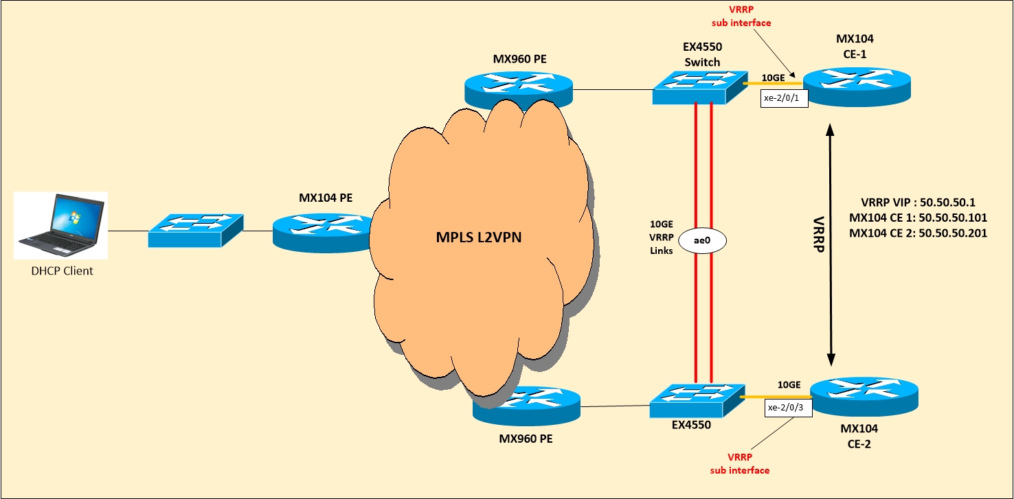
Below model topology will be used where clients (Windows Laptop) is connected to MX104 PE via switch. VRRP is configured with MX104 CE-1 and MX104 CE-2 and both are acting as DHCP Server, however we will be looking at configuration of MX104 CE-1 as same configuration needs to be configured on both.

MX104 PE is connected to MX960 PE over L2VPN which is just extending the L2 domain from client over to DHCP server.

DHCP Model

Ok Lets start by looking at Interface configuration on MX104-CE-1 where xe-2/0/3 link is connected to EX4550 switch and VRRP is running with VRRP VIP as 50.50.50.1 and address on logical interface is 50.50.50.101.

Nothing special till here and no DHCP configuration even.

MX104-CE-1> show configuration logical-systems LS2-CLMB interfaces xe-2/0/3
unit 601 {
 vlan-id 601;
 family inet {
 address 50.50.50.101/24 {
 vrrp-group 201 {
 virtual-address 50.50.50.1;
 priority 200;
 accept-data;
 track {
 route 0.0.0.0/0 routing-instance default priority-cost 101;
 }
 }
 }
 }
}

Ok now lets add DHCP configuration by defining the dhcp-local server under system services hierarchy.

Here we need to define the group with any arbitrary name and interface which will be participating in DHCP msg exchange.

system {
 services {
 dhcp-local-server {
 group dhcp {
 interface xe-2/0/3.601;
 }
 }
 }
}

Once dhcp server has been defined, we will configure DHCP pools to provide addresses to clients.

In same heirachy we can define the dhcp-attributes like lease time, DNS servers and router which suggests the ip address of router in the subnetwork. We have 2 routers providing the DHCP services however as its under VRRP it will be better to give just one address which will be VRRP VIP. In this way in case of any issues on CE-1, VIP will move over to CE-2 and it will be able to assign the addresses.

Range is defined as ip addresses which DHCP server will assign. Lease time is 24 hours in seconds i.e 86400

access {
 address-assignment {
 pool dhcp {
 family inet {
 network 50.50.50.0/24;
 range dhcp {
 low 50.50.50.4;
 high 50.50.50.100;
 }
 dhcp-attributes {
 maximum-lease-time 86400;
 name-server {
 8.8.8.8;
 }
 router {
 50.50.50.1;
 }
 }
 }
 }
 }
}

Once everything is done, as soon as Laptop comes online it will send the request and MX104 will assign the ip address. We will see the messages in just a while but one thing to note is that if you have protect-RE firewall filter configured on loopback0 interface of MX104, it is essential to allow bootps and bootpc messages

term dhcp {
from {
 protocol udp;
 port [ bootpc bootps ];
}
then accept;
}

MX104_CE-1> show dhcp server binding logical-system LS2-CLMB
IP address Session Id Hardware address  Expires State Interface
50.50.50.5 2          68:f7:28:45:14:91 85495   BOUND xe-2/0/3.601

As you can see above, 50.50.50.5 address has been assigned by MX104 and state is BOUND and also listing the hardware address of client machine.

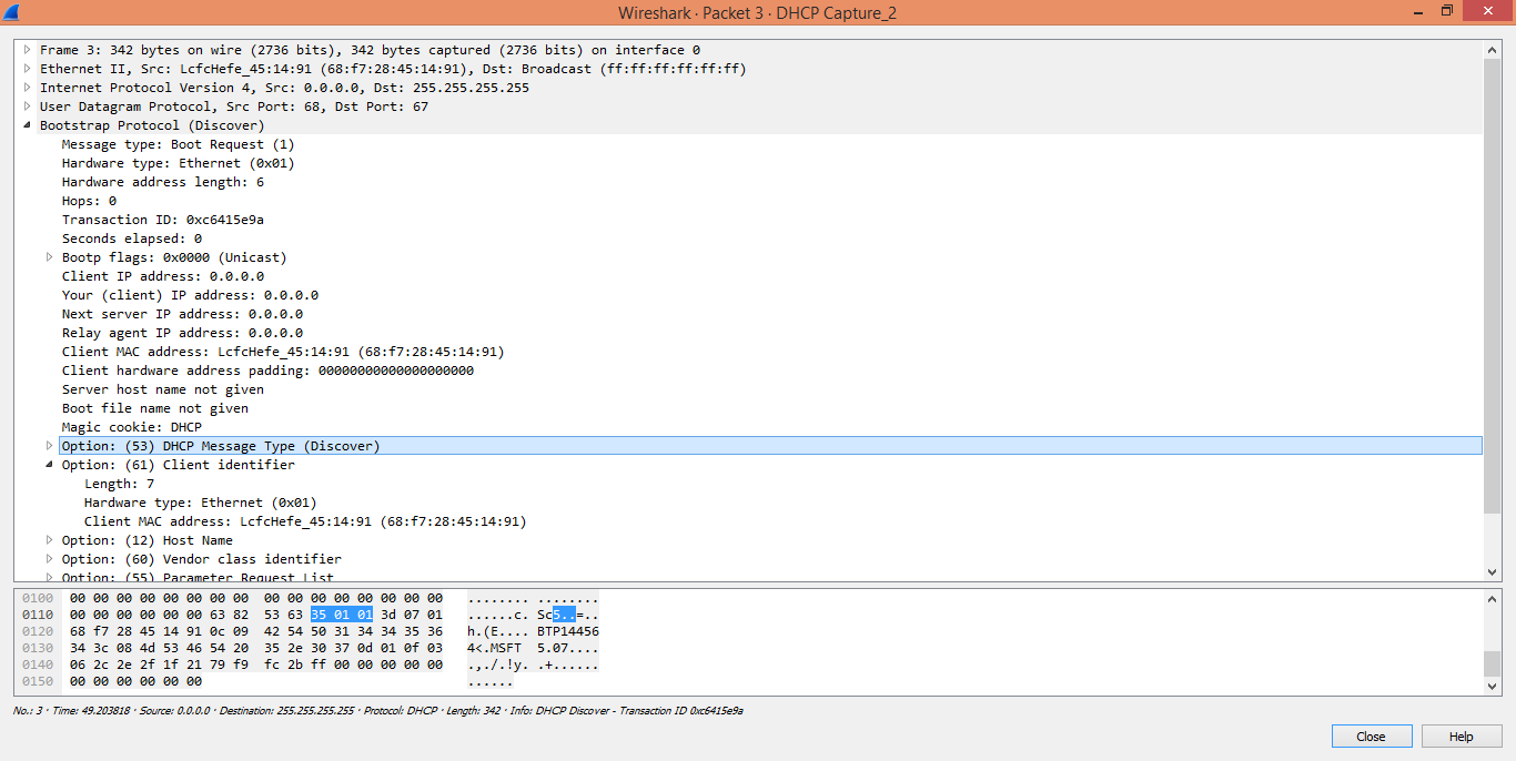
Now lets see how DHCP messages flow. I have shown below the snapshots of wireshark capture for the DHCP messages.

As soon as Laptop comes online or it is connected to LAN, first message it sent is DHCP discover message which is basically a broadcast BOOTP message with frame field as its own mac address as source and all FFs as destination MAC. UDP port number is 68 with destination as 67 so it is basically looks like

UDP 0.0.0.0:68 -> 255.255.255.255:67

As client doesn’t have IP address at this time, it uses 0.0.0.0 as src ip.

68 is standard UDP port assigned for bootp client and 67 for bootp server.

DHCP_1

Once client broadcasts the DHCP discover request, DHCP server sends a DHCP Offer. Src IP Address is physical IP of router which is currently holding the VIP in VRRP case. In our case its MX104 CE-1.

Offer will contain the IP Address 50.50.50.5 as we have already seen in CLI output above along with other parameters which we configured like Lease time, Subnet Mask, Router address, DNS Server etc etc.

DHCP_2

After receiving the Offer and before accepting it, client again sends the broadcast message by including the IP 50.50.50.5 for confirmation.

DHCP_3

At this point, DHCP server sends unicast acknowledgment for it to keep the address and connection is complete.

DHCP Client will periodically sends DHCP Inform messages (both Unicast and Broadcast) to let others know of the address being used.

DHCP_4

Ok so that’s all for DHCP, i hope you liked the post and let me know if you have any feedback or queries.

Mohit Mittal