Category Archives: Automation

Service Assurance with Juniper Paragon Active Assurance (Netrounds)

Hi All, hope you all are well.

In this blog, will look at Juniper’s recent acquisition called Netrounds. Netrounds have been rebranded as Paragon Active Assurance (PAA) which is part of Paragon Automation portfolio and is a programmable, active test and monitoring solution for physical, hybrid, and virtual networks. Unlike passive monitoring approaches, Paragon Active Assurance uses active, synthetic traffic to verify application and service performance at the time of service delivery and throughout the life of the service.

There are various features of PAA however in nutshell, operations teams can use PAA to identify, understand, troubleshoot, and resolve issues before your end users even notice them. This service performance visibility can help decrease incident resolution time by as much as 50%, resulting in greater end-user satisfaction and retention.

We will be using simple topology consisting of a Controller, Test Agents and 2 vMXs to model it in EVE-NG.

eve-ng netrounds juniper active assurance
EVE-NG Topology

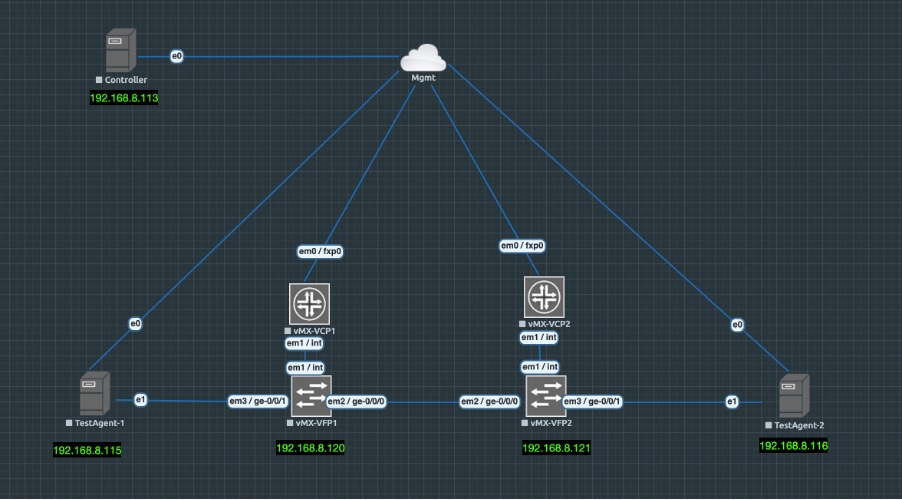
Controller has been instantiated by spinning clean Ubuntu 18.04.05 LTS VM and then added the required controller packages.
 
You can get the Controller up and running by following the below URL:
 
https://www.juniper.net/documentation/us/en/software/active-assurance3.0.0/paa-install/topics/concept/install-os-software.html
 
Controller Version: 3.0.0
vMX version: 18.2R2-S4
Test Agent: 3.0.0.23

Once the controller is up and running and has been licensed, you can open the UI page on the its management address.

In my case its on https://192.168.8.113/ and you will be presented with login screen where after getting authenticated, you will land on Dashboard page.

For us, as expected nothing is here as no configuration has been added via UI.

Once controllers are up, we will add Test Agents (TA) to manage all from single pane of glass.

We will add 2 TAs, and for that we need to build new Linux VM however this time its all prepackaged VM in .qcow2 format which we can download from Controller UI.

Download the .qcow2 format, disk image.

Once downloaded, we will boot the VM using this Qemu image and will get the Test Agent up and running. Now we need to open console to TEST Agent and add the Controller IP in format: <controller-ip>:6000

6000 is important as TA and Controller talk on this port. If you have firewall in between, make sure to allow this port.

Once both TAs are added, they will be shown in the Test Agents Section on the left menu of the Controller as below.

Click on each Test Agent and configure the IP Addresses on Revenue port. In my case its eth1 which is connected to vMXs.

Before we delve more into TAs, let me give you run down of vMXs.

vMXs have OSPF, LDP, RSVP, BGP, running between them. I have configured L2VPN CCC between 2 VMXs.

As you can see below, interface towards TA1 is in vlan 601 and hence we need to accordingly add 601 vlan on TA1 and assign the IP. In my case, I have defined 20.20.20.1/24.

root@vMX-1> show mpls lsp
Ingress LSP: 1 sessions
To From State Rt P ActivePath LSPname
2.2.2.2 1.1.1.1 Up 0 * vmx1-to-vmx2
Total 1 displayed, Up 1, Down 0

Egress LSP: 1 sessions
To From State Rt Style Labelin Labelout LSPname
1.1.1.1 2.2.2.2 Up 0 1 FF 299808 - vmx2-to-vmx1
Total 1 displayed, Up 1, Down 0

Transit LSP: 0 sessions
Total 0 displayed, Up 0, Down 0

root@vMX-1> show connections
CCC and TCC connections [Link Monitoring On]
Legend for status (St): Legend for connection types:
UN -- uninitialized if-sw: interface switching
NP -- not present rmt-if: remote interface switching
WE -- wrong encapsulation lsp-sw: LSP switching
DS -- disabled tx-p2mp-sw: transmit P2MP switching
Dn -- down rx-p2mp-sw: receive P2MP switching
-> -- only outbound conn is up Legend for circuit types:
<- -- only inbound conn is up intf -- interface
Up -- operational oif -- outgoing interface
RmtDn -- remote CCC down tlsp -- transmit LSP
Restart -- restarting rlsp -- receive LSP

Connection/Circuit Type St Time last up # Up trans
l2vpn-1 rmt-if Up Mar 5 13:02:14 2
ge-0/0/1.601 intf Up
vmx1-to-vmx2 tlsp Up
vmx2-to-vmx1 rlsp Up

Another important consideration to make is NTP. Make sure NTP is synced properly on TAs before running the test. You can use any NTP server for this or make your controller as NTP server.

That’s all for vMXs, let me know if you have any particular query on it. We will look at TAs now.

To start the test, Click on ‘New Monitor’ under Monitoring option on left hand menu.

Fill the details and select Element. In our case we have selected 2 Elements, UDP and VOIP UDP which are basically 2 different streams with 2 different profiles going at same time.

Configure each element separately with parameters and Client and Server interface ports.

You can define the threshholds here and frame rates, dscp value of streams.

Press the start button. Once started, we can verify the traffic on vMXs in both Input and Output direction below which suggests that bidirectional traffic is working.


root@vMX-1> show interfaces ge-0/0/1 | match rate | refresh 1

---(refreshed at 2021-03-05 13:22:05 UTC)---

  Input rate     : 185792 bps (59 pps)

  Output rate    : 185792 bps (59 pps)

    FEC Corrected Errors Rate               0

    FEC Uncorrected Errors Rate             0

---(refreshed at 2021-03-05 13:22:06 UTC)---

  Input rate     : 185792 bps (59 pps)

  Output rate    : 185792 bps (59 pps)

    FEC Corrected Errors Rate               0

    FEC Uncorrected Errors Rate             0

---(refreshed at 2021-03-05 13:22:07 UTC)---

  Input rate     : 188064 bps (59 pps)

  Output rate    : 188064 bps (59 pps)

    FEC Corrected Errors Rate               0

    FEC Uncorrected Errors Rate             0

---(refreshed at 2021-03-05 13:22:08 UTC)---

  Input rate     : 188064 bps (59 pps)

  Output rate    : 188064 bps (59 pps)

    FEC Corrected Errors Rate               0

    FEC Uncorrected Errors Rate             0

---(refreshed at 2021-03-05 13:22:09 UTC)---

  Input rate     : 187680 bps (59 pps)

  Output rate    : 187680 bps (59 pps)

    FEC Corrected Errors Rate               0

    FEC Uncorrected Errors Rate             0

---(refreshed at 2021-03-05 13:22:10 UTC)---

  Input rate     : 187680 bps (59 pps)

  Output rate    : 187680 bps (59 pps)

    FEC Corrected Errors Rate               0

    FEC Uncorrected Errors Rate             0

---(refreshed at 2021-03-05 13:22:11 UTC)---

Once stopped. Click on the report at the top and you will get the status of test along with results and graphs.

That’s all from this blog. Its just an introduction to PAA however its capable of doing much much more. We can use the RPM/TWAMP on Routers to get the 2 way or Round trip time measurements from the network which can give you edge before handing over the network to your customers for actual traffic and proactively troubleshoot for any issues.

That’s all for this. I will add more test in next blogs, however till then let me know if you have any queries.

Mohit

Juniper Config Backup on GITLAB

Hi All

In this blog, we will see how we can take the backup of router configs and push it to gitlab for version control.

We will take Juniper routers here for example and build the script in Python and run our task as a cronjob on CentOS 7 to automatically backup the configs onto GITLAB.
We will use power of Git here to store the differentials in configs and we can see the differences in Gitlab UI.

So let’s see how we can achieve it.
Before starting with config backup, let’s build the device store on which we will be running the script or in other words backup will be running. For this we are storing the values in YAML file http://yaml.org/ as dictionary. You can either store the values as list or Dictionary in YAML. You can use json also to store the same data instead of YAML.

Yaml file (.yml)
---
# Add devices here in form Hostname: 'ip address'
  Manchester_MX10003: '10.198.206.3'
  Glasgow_MX10003: '10.198.206.6'
  London_MX104: '10.198.206.9'
  Leeds_MX104: '10.198.206.12'
  Bristol_MX104: '10.198.206.15'

Above are the file contents, where we are storing the data as Key, Value pair where Key is hostname of device and Values are its IP Addresses.

Now our data store is done, we can start with Juniper PYez (https://www.juniper.net/documentation/en_US/junos-pyez/topics/concept/junos-pyez-overview.html) to get the configs first.

We will be importing the Pyez modules, set the .yml input file location and run ‘for’ loop on our dictionary. We will store the backup config files as .txt file with hostnames as Title for easy accessibility. Don’t forget to import yaml module as we will be working on yaml file.

from jnpr.junos import Device
from jnpr.junos.exception import ConnectError
import yaml

input_file = '/home/sun/gitlab/device_list.yml'

for key, value in yaml.load(open(input_file)).items():

    dev_username = test
    dev_password = test
    dev = Device(host=value, user=dev_username, passwd=dev_password, port='830')

    try:
        dev.open()
    except ConnectError as err:
        print ("Cannot connect to device: {0}".format(err))
        sys.exit(1)
    except Exception as err:
        print (err)
        sys.exit(1)

    config = str(dev.cli("show configuration | no-more", warning=False))

    #####Create/Write to Config to File

    file_name = key + '.txt'


   dev.close()

That was pretty simple. Let me know if you have any issues. Now let’s work out how to push it to GIT.

We will be using the subprocess module to do this work for us where we will be running series of commands in serial to put the files across the gitlab. You are starting by going into particular directory which is your starting git project directory. You are looking at each branch within your git project using ‘git branch’ command and then checking out a particular branch on which you to work or store the data. In our case it’s Core_Network. Once you have moved to that, you can move into other specific folders and ‘mv’ your backup .txt files into this folder.

Once that is done, you will use git commands, like ‘git add –all’ to add all files as part of staging. ‘git commit –m “some description”’ to commit the files and then use ‘git push’ to push them to remote gitlab server.

Code will be:

from subprocess import PIPE
from subprocess import Popen
import sys
import os
import yaml
cmds =['cd /home/sun/gitlab/athena-test', 'git branch', 'ls -l', 'git checkout " Core_Network"', 'cd "Core Network"', 'cd "Device backups"', 'mv /home/sun/gitlab/*.txt /home/sun/gitlab/athena-test/"Core Network"/"Device backups"/', 'git add --all', 'git commit -m "Updated config files"', 'git push' ]
encoding = 'utf8'
p = Popen('/bin/sh', stdin=PIPE, stdout=PIPE, stderr=PIPE)
for cmd in cmds:
p.stdin.write(cmd + "\n")
p.stdin.close()
#print p.stdout.read()
print "Push to GitLab Completed"

One main thing you have to keep in mind is that you won’t be able to push the files until unless you have some remote servers configured under your server.

For example, mine is below where I have removed certain values and replaced them with xxx, yyy and ip address.. xxx is username, yyy is password and hostname  is gitlab server address.

sun@ $ git remote -v
origin https://xxx:yyy@<hostname>/athena-test.git (fetch)
origin https://xxx:yyy@<hostname>/athena-test.git (push)

Let’s see this in action by changing the config on one of the router.

write@re0.Manchester.MX10003.uk> edit
Entering configuration mode

write@re0.Manchester.MX10003.uk# run show configuration system services ssh
root-login allow;
protocol-version v2;
max-sessions-per-connection 32;
connection-limit 20;
rate-limit 10;

[edit]
write@re0.Manchester.MX10003.uk# set system services ssh connection-limit 10

[edit]
write@re0.Manchester.MX10003.uk# show | compare
[edit system services ssh]
- connection-limit 20;
+ connection-limit 10;

[edit]
write@re0.Manchester.MX10003.uk# commit
commit complete

Run the script now from CentOS Server

sun@ pwd

/home/sun/gitlab

sun@ $ python git_config_backup.py

Successfully Collected Configuration from Device: Bristol_MX104

Successfully Collected Configuration from Device: Manchester_MX10003

Successfully Collected Configuration from Device: Glasgow_MX10003

Successfully Collected Configuration from Device: London_MX104

Successfully Collected Configuration from Device: Leeds_MX104

Push to GitLab Completed


You can see config was pushed and if we see the gitlab, it’s clearly showing the difference from the previous backup it had. Red one is one that is removed and Green one is what has been added.

So you can use this utility as version control of your configs and once you are happy with the configs you can push them to master for production use 🙂


Gitlab
GitLab side by side comparison


One last thing, if you have to run this as a cronjob on Centos, just edit the crontab file using ‘crontab –e’ and add the path to the script and at what particular time you want to run and that’s all.

I hope you liked this blog. Let me know if you have any queries.


Regards

Mohit

Connecting OpendayLight to Juniper Routers via Netconf

Hi All

In this blog, we will look at configuring Juniper routers via Opendaylight which in turn uses netconf/restconf for making the connection.

Before we can start doing the configuration we need to create a Netconf connector between Opendaylight and Juniper routers. Also before that let’s first see what NETCONF is 🙂

Network Configuration Protocol (NETCONF) provides a mechanism to install, manipulate and delete the configuration of network devices. It uses an Extensible Markup Language (XML) based data encoding for the configuration data as well as the protocol messages. The NETCONF protocol operations are realized as remote procedure calls (RPCs).

OpenDaylight uses YANG modules to access the device via NETCONF and we can do config as well. In this post we will see how to configure ODL for NETCONF connections. This is tried method so please do this as listed and I have seen others methods may not work properly.

Below topology we will be using in this blog.

  • Juniper MXs are running on 18.2R1 and 17.4R1
  • OpendayLight Release is Oxygen 0.8.2


ODL-Netconf-Juniper1) In First instance, you need to enable netconf on Juniper

write@Manchester> show configuration system services netconf
ssh {
    connection-limit 10;
    rate-limit 5;
}
rfc-compliant;
yang-compliant;


2) Download the 0.8.2 Oxygen Tar file from Opendaylight website and untar it.

Command “ tar –xvf karaf-0.8.2.tar.gz

This will create a directory called karaf-0.8.2 in same directory structure.

[root@Opendaylight-2 sun]# ls -l | grep karaf-0.8.2
drwxr-xr-x. 13 root root      4096 Jul 26 15:42 karaf-0.8.2
-rw-rw-r--.  1 sun  sun  358590049 Jul 24 13:46 karaf-0.8.2.tar.gz


3) Now create a file called, 99-netconf-connector.xml and paste the following contents in it


          prefix:sal-netconf-connector
          controller-config
          
10.198.206.3
830 write write false true http://xml.juniper.net/xnm/1.1/xnm?module=configuration&revision=2018-01-01 prefix:netty-event-executor global-event-executor prefix:binding-broker-osgi-registry binding-osgi-broker prefix:dom-broker-osgi-registry dom-broker prefix:netconf-client-dispatcher global-netconf-dispatcher prefix:threadpool global-netconf-processing-executor prefix:scheduled-threadpool global-netconf-ssh-scheduled-executor urn:opendaylight:params:xml:ns:yang:controller:md:sal:connector:netconf?module=odl-sal-netconf-connector-cfg&revision=2015-08-03

You have to change the details for the values mentioned in Red above according to first device you are trying to add. Don’t change anything else. However if your Junos version is other than 18.2 then you need to check the revision number of yang modules and put the correct date for field in Green above.

Once done, save the file.

4)  Now start the opendaylight using command:

[root@Opendaylight-2 sun]# ./karaf-0.8.2/bin/karaf
Apache Karaf starting up. Press Enter to open the shell now...
100% [========================================================================]
Karaf started in 18s. Bundle stats: 388 active, 389 total
    ________                       ________                .__  .__       .__     __
    \_____  \ ______   ____   ____ \______ \ _____  ___.__.|  | |__| ____ |  |___/  |_
     /   |   \\____ \_/ __ \ /    \ |    |  \\__  \ >  ___/|   |  \|    `   \/ __ \\___  ||  |_|  / /_/  >   Y  \  |
    \_______  /   __/ \___  >___|  /_______  (____  / ____||____/__\___  /|___|  /__|
            \/|__|        \/     \/        \/     \/\/            /_____/      \/

Hit '' for a list of available commands
and '[cmd] --help' for help on a specific command.
Hit '' or type 'system:shutdown' or 'logout' to shutdown OpenDaylight.
opendaylight-user@root>


Install following packages, you don’t have to add any other at this moment of time:

feature:install odl-netconf-topology odl-restconf odl-netconf-connector-all

After installing, copy the file 99-netconf-connector.xml created above under directory karaf-0.8.2/etc/opendaylight/karaf/

cp 99-netconf-connector.xml karaf-0.8.2/etc/opendaylight/karaf/


5) After this, using POSTMAN or similar application, send a PUT request to following URL

PUT http://&lt;CONTROLLER-IP-ADDRESS:8181>/restconf/config/network-topology:network-topology/topology/topology-netconf/node/<node-name>

Same as before change the values in Red and Green accordingly for your case.

   node-name
   10.198.206.3
   830
   write
   write
   false
   0
   
    
	 http://xml.juniper.net/xnm/1.1/xnm?module=junos-common-types&revision=2018-01-01
	
	    
	 http://xml.juniper.net/xnm/1.1/xnm?module=module=junos-conf-root&revision=2018-01-01


6) After this restart the opendaylight

opendaylight-user@root>system:shutdown
Confirm: halt instance root (yes/no): yes
opendaylight-user@root>

[root@Opendaylight-2 sun]# ./karaf-0.8.2/bin/karaf
Apache Karaf starting up. Press Enter to open the shell now...
opendaylight-user@root>

At this point you should some messages like as mentioned in Karaf_Logs after adding the netconf-connector. Let it run..it may take 10-20 minutes from here which is basically ODL is pulling all the Juniper Yang modules in its cache/schema folder.

Once that is done you should see the below message in karaf log which you can see using log:tail from opendaylight shell prompt.

| INFO  | sing-executor-22 | NetconfDevice   | 304 - org.opendaylight.netconf.sal-netconf-connector - 1.7.2 | RemoteDevice{Manchester}: Netconf connector initialized successfully

Once you get the message, your node has been mounted which you can check using GET request at following URL

GET http:// <CONTROLLER-IP-ADDRESS:8181/restconf/operational/network-topology:network-topology/topology/topology-netconf/node/<Node-name>/yang-ext:mount/

GET-Mount

Now its ready to configure 🙂

Let’s configure a sample L3VPN using this

See the snapshot which is basically a PUT request with XML payload

Send-L3VPN-Request

Lets’s verify

write@Manchester> show configuration routing-instances odl-test
instance-type vrf;
interface xe-0/2/0.4000;
route-distinguisher 10.198.206.41:4000;
vrf-target target:2856:4000;
vrf-table-label;
routing-options {
    multipath;
    protect core;
}
protocols {
    bgp {
        group ebgp {
            type external;
            peer-as 65101;
            as-override;
            neighbor 7.7.7.7 {
                authentication-key "$9$CuyoAORhclMLNylJDkP3nylKvWx"; ## SECRET-DATA
                bfd-liveness-detection {
                    minimum-interval 100;
                    multiplier 3;
                }
            }
        }
    }
}


Here you go.. its working 🙂

That’s all for today.. I will do a separate blog for other service configurations via ODL. Let me know if you have any questions.


Bbye

Mohit

PCEP Initiated LSP using OpenDayLight and Juniper vMX

Hi All

In this post, we will look at Open day light controller working with Juniper vMXs and how we can use the controller to get the BGP, BGP-LS and PCEP working. Once everything is up and running we will use the Controller to initiate the PCEP initiated MPLS LSPs between 2 VMXs.

Sounds interesting? Let’s see how we can achieve this.

Before I go further, if you want to check anything on PCEP and some of its concept, I did a post on Juniper Northstar Controller some time ago which you can check.

https://networkzblogger.com/2017/03/17/juniper-northstar-wan-sdn-controller/

Below is the topology we will be using where all Juniper VMXs are loaded in Virtual Control Plane mode and they have fxp0 interface in 192.168.71.x subnet. Open day light controller version is Nitrogen and we have booted it on CentOS 7.5 version.

There is Windows VM in same subnet also from where we will run the REST APIs calls to Open day light using POSTMAN App.

Topology Diagram
Topology Diagram


We will divide the post into 3 parts.

  • Configuring BGP/BGP-Link state between ODL and 192.168.71.24 VMX-3.
  • Configuring PCEP session between all VMXs and ODL
  • Initiate MPLS LSP from ODL using PCEP

I am assuming that you already know how to start an ODL controller. However if you don’t know let me know and I can help you.

So lets start with 1) Configuring BGP/BGP-Link state between ODL and 192.168.71.24 VMX-3.

If you already don’t know, Open day light versions in recent times doesn’t come auto-installed with all the features. You have to manually add them. You don’t need to download them individually. It’s just you need to activate them.

We will be configure the BGP and BGP-LS on VMX-3 first

Standard BGP config with IPv4 Unicast address family however for BGP-LS we have to enable a separate family traffic-engineering additionally.

root@VMX-3> show configuration protocols bgp
group opendaylight {
 type internal;
 description Controller;
 local-address 192.168.71.24;
 family inet {
 unicast;
 }
 family traffic-engineering {
 unicast;
 }
 peer-as 2856;
 neighbor 192.168.71.22;
}

On ODL side, First install the BGP and restconf feature on karaf console using command

feature:install odl-restconf odl-bgpcep-bgp

Then using REST API we will enable the BGP Router-ID with Link State family

POST URL : 192.168.71.22:8181/restconf/config/openconfig-network-instance:network-instances/network-instance/global-bgp/openconfig-network-instance:protocols

POST Request_BGP Router ID

Then Configure the peer 192.168.71.24 with specific BGP Parameters and families

POST URL: 192.168.71.22:8181/restconf/config/openconfig-network-instance:network-instances/network-instance/global-bgp/openconfig-network-instance:protocols/protocol/openconfig-policy-types:BGP/bgp-test-odl/bgp/neighbors

POST Request_BGP Peer

We can check the status of BGP peering off course from VMX side but let’s see what comes up from ODL side

GET URL: 192.168.71.22:8181/restconf/operational/bgp-rib:bgp-rib/rib/bgp-test-odl/peer/bgp:%2F%2F3.3.3.3

GET Request_BGP Peering

From VMX side:

root@VMX-3> show bgp neighbor
Peer: 192.168.71.22+27755 AS 2856 Local: 192.168.71.24+179 AS 2856
 Description: Controller
 Group: opendaylight Routing-Instance: master
 Forwarding routing-instance: master
 Type: Internal State: Established Flags: <Sync>
 Last State: OpenConfirm Last Event: RecvKeepAlive
 Last Error: None
 Options: <Preference LocalAddress LogUpDown AddressFamily PeerAS Refresh>
 Options: <VpnApplyExport DropPathAttributes>
 Address families configured: inet-unicast te-unicast
 Path-attributes dropped: 128
 Local Address: 192.168.71.24 Holdtime: 90 Preference: 170
 Number of flaps: 2
 Last flap event: RecvNotify
 Error: 'Cease' Sent: 0 Recv: 33
 Peer ID: 192.168.71.22 Local ID: 3.3.3.3 Active Holdtime: 90
 Keepalive Interval: 30 Group index: 0 Peer index: 0 SNMP index: 0
 I/O Session Thread: bgpio-0 State: Enabled
 BFD: disabled, down
 NLRI for restart configured on peer: inet-unicast te-unicast


BGP-LS configuration we did will be used to advertise the Traffic Engineering database to Controller. You can see the routes advertised using lsdist.0 table in juniper.

Snippet below:

root@VMX-3> show route table lsdist.0
lsdist.0: 11 destinations, 11 routes (11 active, 0 holddown, 0 hidden)
+ = Active Route, - = Last Active, * = Both
NODE { AS:2856 Area:0.0.0.0 IPv4:2.2.2.2 OSPF:0 }/1152
 *[OSPF/10] 02:02:38
 Fictitious
NODE { AS:2856 Area:0.0.0.0 IPv4:3.3.3.3 OSPF:0 }/1152
 *[OSPF/10] 02:02:43
 Fictitious
NODE { AS:2856 Area:0.0.0.0 IPv4:4.4.4.4 OSPF:0 }/1152
 *[OSPF/10] 02:02:38
 Fictitious
NODE { AS:2856 Area:0.0.0.0 IPv4:4.4.4.4-192.168.71.26 OSPF:0 }/1152
 *[OSPF/10] 02:02:31
 Fictitious
LINK { Local { AS:2856 Area:0.0.0.0 IPv4:2.2.2.2 }.{ IPv4:192.168.71.23 } Remote { AS:2856 Area:0.0.0.0 IPv4:4.4.4.4-192.168.71.26 }.{ } OSPF:0 }/1152
 *[OSPF/10] 02:02:31
 Fictitious
..
…
…


2) Now let’s configure the PCEP

On VMX (This will be repeated on all with change in local address)

root@VMX-3> show configuration protocols pcep
pce odl {
 local-address 192.168.71.24;
 destination-ipv4-address 192.168.71.22;
 destination-port 4189;
 pce-type active stateful;
 lsp-provisioning;
 p2mp-lsp-report-capability;
}

If you have any firewall, make sure to allow port 4189 between Controller and VMXs.

On ODL, we need to install odl-bgpcep-pcep feature

There is no other config to do. As soon as you install this feature, you should see PCEP status up.

Let’s see it from VMX-4


root@VMX-4> show path-computation-client status
Session Type            Provisioning Status
odl     Stateful Active On           Up

LSP Summary
 Total number of LSPs : 0
 Static LSPs : 0
 Externally controlled LSPs : 0
 Externally provisioned LSPs : 0/16000 (current/limit)
 Orphaned LSPs : 0

odl (main)
 Delegated : 0
 Externally provisioned : 0

From ODL side:

GET Request_PCEP Status

3)      PCEP Initiated LSP

Now, we will configure the LSP from VMX-3 to VMX-4 between their Loopback IPs.

POST URL: 192.168.71.22:8181/restconf/operations/network-topology-pcep:add-lsp

You can see we haven’t given any ERO while provisioning the LSP. ODL has auto calculated the path and you can verify in VMX-3

PCEP LSP ADD with No Ero

root@VMX-3> show mpls lsp name test-pcep-2 extensive
Ingress LSP: 1 sessions

4.4.4.4
 From: 3.3.3.3, State: Up, ActiveRoute: 0, LSPname: test-pcep-2
 ActivePath: (primary)
 LSPtype: Externally provisioned, Penultimate hop popping
 LSP Control Status: Externally controlled
 LoadBalance: Random
 Encoding type: Packet, Switching type: Packet, GPID: IPv4
 LSP Self-ping Status : Enabled
 *Primary State: Up, Preference: 200
 Priorities: 0 0
 External Path CSPF Status: external
 SmartOptimizeTimer: 180
 Flap Count: 0
 MBB Count: 0
 Received RRO (ProtectionFlag 1=Available 2=InUse 4=B/W 8=Node 10=SoftPreempt 20=Node-ID):
 192.168.71.26(Label=0)
 12 May 24 12:10:08.334 Self-ping ended successfully
 11 May 24 12:10:07.830 EXTCTRL LSP: Sent Path computation request and LSP status
 10 May 24 12:10:07.830 EXTCTRL_LSP: Computation request/lsp status contains: signalled bw 0 req BW 0 admin group(exclude 0 include any 0 include all 0) priority setup 0 hold 0
 9 May 24 12:10:07.829 Selected as active path
 8 May 24 12:10:07.828 EXTCTRL LSP: Sent Path computation request and LSP status
 7 May 24 12:10:07.828 EXTCTRL_LSP: Computation request/lsp status contains: signalled bw 0 req BW 0 admin group(exclude 0 include any 0 include all 0) priority setup 0 hold 0
 6 May 24 12:10:07.828 Up
 5 May 24 12:10:07.828 Self-ping started
 4 May 24 12:10:07.828 Self-ping enqueued
 3 May 24 12:10:07.828 Record Route: 192.168.71.26(Label=0)
 2 May 24 12:10:07.824 Originate Call
 1 May 24 12:10:07.824 EXTCTRL_LSP: Received setup parameters ::
 Created: Thu May 24 12:10:07 2018
Total 1 displayed, Up 1, Down 0


You can do various operations like Deleting LSP, Modifying LSP etc from REST API.

One thing which we can’t do at the moment using PCEP is configuring Point to Multipoint LSP as standard is still being drafted for this but I hope it will come out soon.

So that’s all for now, I hope you enjoyed it and let me know your feedback.


Regards

Mohit


Segment Routing v/s RSVP-TE?

SR (Segment Routing) is new and trending topic these days in Telecom Networks. It’s promising and some vendors are pushing for it because of the way we can leverage SDN Controller to steer the traffic through the Network plus how it will remove need of LDP/RSVPE-TE from core however i think there are still some of the use cases where it lacks some capabilities currently. I hope in future all these areas will be fixed and SR becomes THE Option of choice for all Service Providers. These are all my opinions and it would be good to know your views on it.

1)      Bandwidth Reservation issue –> Using SR we can’t reserve the bandwidth in our Network for each LSP as we can do with RSVP-TE. Bandwidth reservation can be critical in some Service provider/Broadcast networks to provide the customer with dedicated bandwidth. We can argue that Controller at the Top can look at the whole Network and would be able to easily manage the reservations however Controller is a single point of failure and I don’t think we can depend upon Controller for this crucial behaviour.?

2)      Lack of Multicast P2MP Support –> Multicast proposes more challenge for the segment routing. SR can only replace Point to point LDP/RSVP-TE however some of the Telecom Networks uses P2MP Multicast services as part of NG-MVPN and for those we still need to depend on RSVP-TE . Moreover MPLS-based multicast solutions have matured now after many years’ of development. I think keeping 2 Technologies i.e one for P2P L2/L3VPN and other for P2MP MVPN will add complexity only to network.

3)      Depth of MPLS Label Stack –> We know that forwarding packets need to push a SR header with a list of segments(labels). Now there are 2 main types of SR Labels. One is Node and other is Adjacency (link). To provide granularity to route the traffic via 15-20 hops we need to push more Adjacency labels at Ingress PE accordingly. This depth of label stack may be a challenge for some type of devices.

Plz see some of the labels stack present in hardware:  (Courtesy: NANOG.org)

Linux (kernel 4.10): 2-3 SID’s

Low end off the shelf (merchant) silicon, e.g. BCM Trident2: 3-5 SID’s

High end off the shelf (merchant) silicon, e.g BCM Jericho1 : 4-7 SID’s

Vendor’ silicon, e.g. Juniper’ Trio: 4-10+ SID’s

Even though Vendor may be able to support 15-20 Label stack, we can end up in payload efficiency and MTU issues i.e. because of big size of the header will reduce the efficiency of payload.

4)      State Issues –> One major advantage for segment routing proposed was that the State is only maintained at the head-end. No state is maintained at mid-points and tail-ends. This is good in case if we have Node and Adjacency/Link labels only however there are proposals for Prefix segment Labels also which will increase the state on all the points in network and I don’t think behaviour will be different from LDP/RSVP-TE then.

In case of centrally controlled environment where Controller will take care of everything it will be difficult for Operations Teams to troubleshoot in case anything goes wrong in Network as they need to know the architecture of each device whether it is capable of getting around the Label stack issue via that device. We may be thinking of putting low end devices near to Customer edge as PEs and high end in middle of core, however due to label stack issue we may need to put high end routers only everywhere.

I am not against SR however i would be really pleased if these issues can be taken care or already available (i may well be living in old times) however from my perspective, there is scalability issue which limits application scenarios for segment routing. It may be better for cases where service provider is mostly providing  unicast L2/L3VPN services.

Let me know your views on this and how you are using SR in your environment 🙂