Tag Archives: Alcatel

DHCP Server on Juniper MX104

In this blog, we will discuss about configuration of DHCP for IPv4 on Junos particularly for MX104. MX router will act as a DHCP Local server which will assign IP Addresses to clients from the DHCP pool configured.

To configure DHCP as local server we need to apply the following license on MX which is paid license over the top.

subscriber-address-assignment – Radius/SRC Address Pool Assignment

subscriber-ip   – Dynamic and Static IP

For those who doesn’t want to buy license, they have option of configuring the DHCP as relay however for which server will be external and not internal.

With this blog, we will look at configuration of router acting as DHCP server. Relay configuration is not part of this current blog.

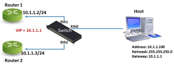
Below model topology will be used where clients (Windows Laptop) is connected to MX104 PE via switch. VRRP is configured with MX104 CE-1 and MX104 CE-2 and both are acting as DHCP Server, however we will be looking at configuration of MX104 CE-1 as same configuration needs to be configured on both.

MX104 PE is connected to MX960 PE over L2VPN which is just extending the L2 domain from client over to DHCP server.

DHCP Model

Ok Lets start by looking at Interface configuration on MX104-CE-1 where xe-2/0/3 link is connected to EX4550 switch and VRRP is running with VRRP VIP as 50.50.50.1 and address on logical interface is 50.50.50.101.

Nothing special till here and no DHCP configuration even.

MX104-CE-1> show configuration logical-systems LS2-CLMB interfaces xe-2/0/3
unit 601 {
 vlan-id 601;
 family inet {
 address 50.50.50.101/24 {
 vrrp-group 201 {
 virtual-address 50.50.50.1;
 priority 200;
 accept-data;
 track {
 route 0.0.0.0/0 routing-instance default priority-cost 101;
 }
 }
 }
 }
}

Ok now lets add DHCP configuration by defining the dhcp-local server under system services hierarchy.

Here we need to define the group with any arbitrary name and interface which will be participating in DHCP msg exchange.

system {
 services {
 dhcp-local-server {
 group dhcp {
 interface xe-2/0/3.601;
 }
 }
 }
}

Once dhcp server has been defined, we will configure DHCP pools to provide addresses to clients.

In same heirachy we can define the dhcp-attributes like lease time, DNS servers and router which suggests the ip address of router in the subnetwork. We have 2 routers providing the DHCP services however as its under VRRP it will be better to give just one address which will be VRRP VIP. In this way in case of any issues on CE-1, VIP will move over to CE-2 and it will be able to assign the addresses.

Range is defined as ip addresses which DHCP server will assign. Lease time is 24 hours in seconds i.e 86400

access {
 address-assignment {
 pool dhcp {
 family inet {
 network 50.50.50.0/24;
 range dhcp {
 low 50.50.50.4;
 high 50.50.50.100;
 }
 dhcp-attributes {
 maximum-lease-time 86400;
 name-server {
 8.8.8.8;
 }
 router {
 50.50.50.1;
 }
 }
 }
 }
 }
}

Once everything is done, as soon as Laptop comes online it will send the request and MX104 will assign the ip address. We will see the messages in just a while but one thing to note is that if you have protect-RE firewall filter configured on loopback0 interface of MX104, it is essential to allow bootps and bootpc messages

term dhcp {
from {
 protocol udp;
 port [ bootpc bootps ];
}
then accept;
}

MX104_CE-1> show dhcp server binding logical-system LS2-CLMB
IP address Session Id Hardware address  Expires State Interface
50.50.50.5 2          68:f7:28:45:14:91 85495   BOUND xe-2/0/3.601

As you can see above, 50.50.50.5 address has been assigned by MX104 and state is BOUND and also listing the hardware address of client machine.

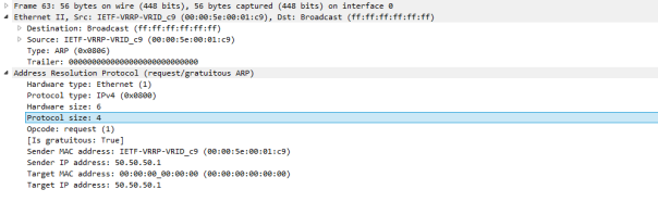
Now lets see how DHCP messages flow. I have shown below the snapshots of wireshark capture for the DHCP messages.

As soon as Laptop comes online or it is connected to LAN, first message it sent is DHCP discover message which is basically a broadcast BOOTP message with frame field as its own mac address as source and all FFs as destination MAC. UDP port number is 68 with destination as 67 so it is basically looks like

UDP 0.0.0.0:68 -> 255.255.255.255:67

As client doesn’t have IP address at this time, it uses 0.0.0.0 as src ip.

68 is standard UDP port assigned for bootp client and 67 for bootp server.

DHCP_1

Once client broadcasts the DHCP discover request, DHCP server sends a DHCP Offer. Src IP Address is physical IP of router which is currently holding the VIP in VRRP case. In our case its MX104 CE-1.

Offer will contain the IP Address 50.50.50.5 as we have already seen in CLI output above along with other parameters which we configured like Lease time, Subnet Mask, Router address, DNS Server etc etc.

DHCP_2

After receiving the Offer and before accepting it, client again sends the broadcast message by including the IP 50.50.50.5 for confirmation.

DHCP_3

At this point, DHCP server sends unicast acknowledgment for it to keep the address and connection is complete.

DHCP Client will periodically sends DHCP Inform messages (both Unicast and Broadcast) to let others know of the address being used.

DHCP_4

Ok so that’s all for DHCP, i hope you liked the post and let me know if you have any feedback or queries.

Mohit Mittal


ARP, InARP, RARP, Proxy ARP & Gratuitous ARP?? Whats this all about!!

There are lots of Arp terms in Network field today i.e. ARP, RARP, InARP, Proxy ARP and Gratuitous ARP. This was really confusing for me atleast in my early networking days and I am sure people who are new to networking must be in same situation. So I thought of putting the details here in order to alleviate their confusion. So let’s start

 1) ARP (Address Resolution Protocol)

ARP or Address Resolution protocol is a protocol as its name states which works on TCP/IP Layer 2. Networking between devices can’t be done without using this protocol which basically helps in getting the mac-address of connected router or gateway from IP Address. So for example, host/computer is connected to Router over Ethernet and we have manually configured IP Addresses on both sides with Router acting as Gateway for Host computer. Before Host can send packet to Router, it needs to build Layer 2 Frame and this frame encapsulates Packet including Payload/Date. You know that Frame has Source MAC-Address and Destination MAC-Address fields apart from other fields. So host can take out source-mac address from value burned in its NIC (Network Interface card) however it won’t be knowing the destination mac-address and in order to get the value of destination mac address host uses ARP. So Host will send broadcast ARP request message (destination FF:FF:FF:FF:FF:FF MAC address), which is accepted by all computers, requesting an answer for router’s gateway mac-address which is returned by Router in form for Arp-reply as a unicast.

APR_Packet Format

54:1e:56:f7:7d:4a > ff:ff:ff:ff:ff:ff, ethertype 802.1Q (0x8100), length 46: vlan 602, p 0, ethertype ARP, arp who-has 20.20.20.20 tell 20.20.20.200

00:00:00:5e:00:00 > 54:1e:56:f7:7d:4a, ethertype 802.1Q (0x8100), length 64: vlan 602, p 0, ethertype ARP, arp reply 20.20.20.20 is-at 00:00:00:5e:00:00

2) InARP ( Inverse ARP)

Now what is Inverse Arp then? Inverse ARP as you might guess is the opposite of ARP.  Instead of using layer 3 IP address to find a layer 2 MAC address, Inverse ARP uses layer 2 MAC addresses to find a layer 3 IP address.

Inverse ARP was mostly used by Framerelay and ATM Networks to map the DLCI to IP Address. So router basically asks the IP Address of destination or other end of PVC by listing DLCI for that router.

3) RARP (Reverse ARP)

Reverse ARP is same as Inverse ARP however it was mainly used for device configuration. In InARP IP Address of remote end was being asked however RARP task is to get the IP Address for its own purpose.

A network administrator creates a table in a local area network’s gateway router that maps the physical machine (or Media Access Control – MAC address) addresses to corresponding IP Addresses. When a new machine is set up, its RARP client program requests it’s IP Address from the gateway router. Assuming that an entry has been set up in the router table, the RARP server will return the IP address to the machine which can store it for future use.

Reverse ARP has been deprecated and replaced by BOOTP which was then later replaced by DHCP.

4) Proxy ARP

As we mentioned above that the ARP is basically to find out Layer 2 address from Layer 3 IP Address. Now suppose host is connected to router over Ethernet and host has one address 10.10.0.1/16 and router has 10.10.10.0/24.

Host wants to resolve the ARP for 10.10.0.100 and thinks that Router is also in same subnet so should be able to get the mac-address however as Routers by design limit broadcast domains so won’t be sending the arp reply back and request will be rejected. If on the other hand router has any other interface connected to 10.10.0.0/16 network and proxy-arp is enabled, in that case Router will send the arp reply to host by listing its own mac-address basically acting as proxy for destination Network. In this case we don’t have to change the netmask of host and it will work fine.

On Cisco interfaces, when we configure “no ip proxy-arp”, we are disabling this behaviour.

5) Gratuitous ARP

Gratuitous ARP is by far the interesting version of ARP and lets see how gratuitous ARP works. We will go through 2 use cases here:

Firstly let’s discuss some of the properties of GARP

  • Both source and destination IP in the packet are the IP of the host issuing the gratuitous ARP
  • The destination MAC address is the broadcast MAC address (ff:ff:ff:ff:ff:ff) . This means the packet will be flooded to all ports on a switch
  • No reply is expected

1st use case of GARP is finding duplicate IP Address on LAN. Host which wakes up lets say after reboot sends GARP by putting the Sender IP address and Target IP Address as its own IP and broadcast the frame using Ethernet II destination address of all FFs.

It is not expecting any reply however if someone replies back with mac-address corresponding to Target IP Address then it means that IP address is being used somewhere else in LAN which is a problem. In this way host can detect duplicates.

2nd use case of GARP is case of redundancy protocols like VRRP/HSRP. VRRP (Virtual Redundancy Routing Protocol) or HSRP works by providing redundant physical gateways to host reachable over same Virtual address in order for Host to reach destination networks even though one physical router is down.

GARP_VRRP

VRRP has VIP (Virtual IP) concept which is shared among 2 VRRP routers and one of them is Active at any one time and holds Virtual MAC-Address corresponding to this VIP. Whenever host requests for ARP for 10.1.1.1, Master router will reply back with Virtual MAC Address.

Now we know that Switch updates its MAC Address table by looking at Mac address being learned on which port. Assuming Router 1 is Master currently, Switch will have entry in its table for Virtual Mac address learnt via Eth1 interface.

Let’s suppose that Router 1 goes down and in that case Router 2 sends GARP forcing switch to update its MAC-address table in order for it to update new location of Virtual MAC address reachable over new port i.e Eth2.

In this way, Host never sees an issue and packets sent by it will always egress a correct port.

Format of Gratuitous ARP

GARP Format

So that’s all, I hope you enjoyed this blog and I was able to clear some of your confusion. Let me know if you still have any doubt.

Thanks

Mohit Mittal

MC – LAG (Multi-Chassis LAG)

Networks of today demands lot of redundancy, be it link level redundancy or device level. Service providers employ various methods to provide this level of service for their customers and one of way is Link Aggregation Group (LAG) where multiple Ethernet links are combined to form a single aggregated group, thereby increasing bandwidth and providing redundancy. This layer 2 transparency is achieved by the LAG using a single MAC address for all the device’s ports in the LAG group. LAG uses a control protocol called LACP for its operation.

Instead of having multiple link i.e 2, 4 or 8 aggregated in one Lag, vendors suggested a proprietary solution to have the device level redundancy built as well in Lag and result was Multi-chassis Lag (MC-LAG). As this is proprietary solution, all the vendors do support it but with little difference from one another. Cisco calls this solution as Multichassis Ether Channel, Alcatel calls its MC-LAG.

The CE (Customer Edge) device is completely unaware that its Ethernet links that belong to the same LAG (Etherchannel in Cisco) are connected to two separate PE (Provider Edge) devices. We can assume PE device here as Alcatel 7750. The two PE routers each have one LAG connected to the same CE device. At a time, only one PE router’s LAG ports are active and carrying traffic. The other PE router’s LAG ports are standby and only become active when failure is detected in the active links. The PE routers perform election to decide the active and standby router.

Picture1

If you see the above figure, from CE’s perspective, all 4 ports belonging to a LAG are connected to a single service provider device (here PEs). All 4 ports are active, but only 2 ports are UP at a time; the other 2 ports are in DOWN state. On the both PE routers, as before we have to create a regular LAG towards the CE device and on top of that we configure MC-LAG separately where we define MC-LAG peer (i.e. 2nd PE address) and LACP parameters. The MC-LAG control protocol information is exchanged between PE routers. This exchange results in active/standby selection, and ensures only one PE router’s ports are active and carrying traffic.  MC-LAG control protocol runs only between MC-LAG peers. Both PE routers send an exactly same {Admin Key, System ID, System Priority} information in the LACP packets.

Link Aggregation Control Protocol (LACP) detects multiple links available between two devices and configures them to use as an aggregate bandwidth. The two sides detect the availability of the other side by sending LACP packets. One end is an Actor, while the other end is the Partner. During LACP negotiation, (Admin Key, System ID, System Priority) identifies the LAG instance. So, for a LAG, all participating ports on that device must have the same values for these 3 fields.


Regards

Mohit Mittal