Tag Archives: Controller

Connecting OpendayLight to Juniper Routers via Netconf

Hi All

In this blog, we will look at configuring Juniper routers via Opendaylight which in turn uses netconf/restconf for making the connection.

Before we can start doing the configuration we need to create a Netconf connector between Opendaylight and Juniper routers. Also before that let’s first see what NETCONF is 🙂

Network Configuration Protocol (NETCONF) provides a mechanism to install, manipulate and delete the configuration of network devices. It uses an Extensible Markup Language (XML) based data encoding for the configuration data as well as the protocol messages. The NETCONF protocol operations are realized as remote procedure calls (RPCs).

OpenDaylight uses YANG modules to access the device via NETCONF and we can do config as well. In this post we will see how to configure ODL for NETCONF connections. This is tried method so please do this as listed and I have seen others methods may not work properly.

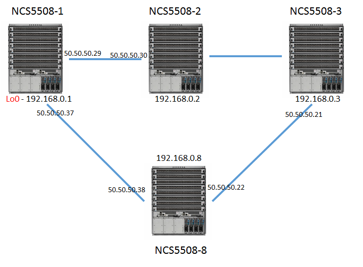
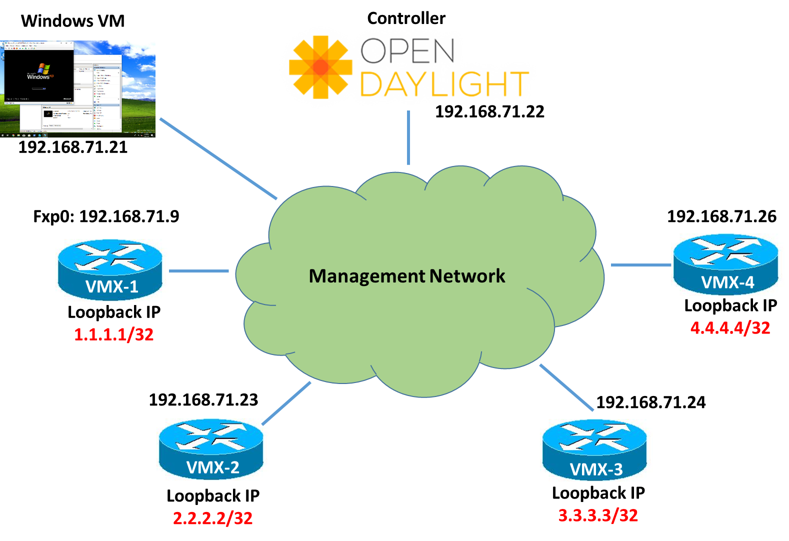
Below topology we will be using in this blog.

  • Juniper MXs are running on 18.2R1 and 17.4R1
  • OpendayLight Release is Oxygen 0.8.2


ODL-Netconf-Juniper1) In First instance, you need to enable netconf on Juniper

write@Manchester> show configuration system services netconf
ssh {
    connection-limit 10;
    rate-limit 5;
}
rfc-compliant;
yang-compliant;


2) Download the 0.8.2 Oxygen Tar file from Opendaylight website and untar it.

Command “ tar –xvf karaf-0.8.2.tar.gz”

This will create a directory called karaf-0.8.2 in same directory structure.

[root@Opendaylight-2 sun]# ls -l | grep karaf-0.8.2
drwxr-xr-x. 13 root root      4096 Jul 26 15:42 karaf-0.8.2
-rw-rw-r--.  1 sun  sun  358590049 Jul 24 13:46 karaf-0.8.2.tar.gz


3) Now create a file called, 99-netconf-connector.xml and paste the following contents in it


          prefix:sal-netconf-connector
          controller-config
          
10.198.206.3
830 write write false true http://xml.juniper.net/xnm/1.1/xnm?module=configuration&revision=2018-01-01 prefix:netty-event-executor global-event-executor prefix:binding-broker-osgi-registry binding-osgi-broker prefix:dom-broker-osgi-registry dom-broker prefix:netconf-client-dispatcher global-netconf-dispatcher prefix:threadpool global-netconf-processing-executor prefix:scheduled-threadpool global-netconf-ssh-scheduled-executor urn:opendaylight:params:xml:ns:yang:controller:md:sal:connector:netconf?module=odl-sal-netconf-connector-cfg&revision=2015-08-03

You have to change the details for the values mentioned in Red above according to first device you are trying to add. Don’t change anything else. However if your Junos version is other than 18.2 then you need to check the revision number of yang modules and put the correct date for field in Green above.

Once done, save the file.

4)  Now start the opendaylight using command:

[root@Opendaylight-2 sun]# ./karaf-0.8.2/bin/karaf
Apache Karaf starting up. Press Enter to open the shell now...
100% [========================================================================]
Karaf started in 18s. Bundle stats: 388 active, 389 total
    ________                       ________                .__  .__       .__     __
    \_____  \ ______   ____   ____ \______ \ _____  ___.__.|  | |__| ____ |  |___/  |_
     /   |   \\____ \_/ __ \ /    \ |    |  \\__  \ >  ___/|   |  \|    `   \/ __ \\___  ||  |_|  / /_/  >   Y  \  |
    \_______  /   __/ \___  >___|  /_______  (____  / ____||____/__\___  /|___|  /__|
            \/|__|        \/     \/        \/     \/\/            /_____/      \/

Hit '' for a list of available commands
and '[cmd] --help' for help on a specific command.
Hit '' or type 'system:shutdown' or 'logout' to shutdown OpenDaylight.
opendaylight-user@root>


Install following packages, you don’t have to add any other at this moment of time:

feature:install odl-netconf-topology odl-restconf odl-netconf-connector-all

After installing, copy the file 99-netconf-connector.xml created above under directory karaf-0.8.2/etc/opendaylight/karaf/

cp 99-netconf-connector.xml karaf-0.8.2/etc/opendaylight/karaf/


5) After this, using POSTMAN or similar application, send a PUT request to following URL

PUT http://&lt;CONTROLLER-IP-ADDRESS:8181>/restconf/config/network-topology:network-topology/topology/topology-netconf/node/<node-name>

Same as before change the values in Red and Green accordingly for your case.

   node-name
   10.198.206.3
   830
   write
   write
   false
   0
   
    
	 http://xml.juniper.net/xnm/1.1/xnm?module=junos-common-types&revision=2018-01-01
	
	    
	 http://xml.juniper.net/xnm/1.1/xnm?module=module=junos-conf-root&revision=2018-01-01


6) After this restart the opendaylight

opendaylight-user@root>system:shutdown
Confirm: halt instance root (yes/no): yes
opendaylight-user@root>

[root@Opendaylight-2 sun]# ./karaf-0.8.2/bin/karaf
Apache Karaf starting up. Press Enter to open the shell now...
opendaylight-user@root>

At this point you should some messages like as mentioned in Karaf_Logs after adding the netconf-connector. Let it run..it may take 10-20 minutes from here which is basically ODL is pulling all the Juniper Yang modules in its cache/schema folder.

Once that is done you should see the below message in karaf log which you can see using log:tail from opendaylight shell prompt.

| INFO  | sing-executor-22 | NetconfDevice   | 304 - org.opendaylight.netconf.sal-netconf-connector - 1.7.2 | RemoteDevice{Manchester}: Netconf connector initialized successfully

Once you get the message, your node has been mounted which you can check using GET request at following URL

GET http:// <CONTROLLER-IP-ADDRESS:8181/restconf/operational/network-topology:network-topology/topology/topology-netconf/node/<Node-name>/yang-ext:mount/

GET-Mount

Now its ready to configure 🙂

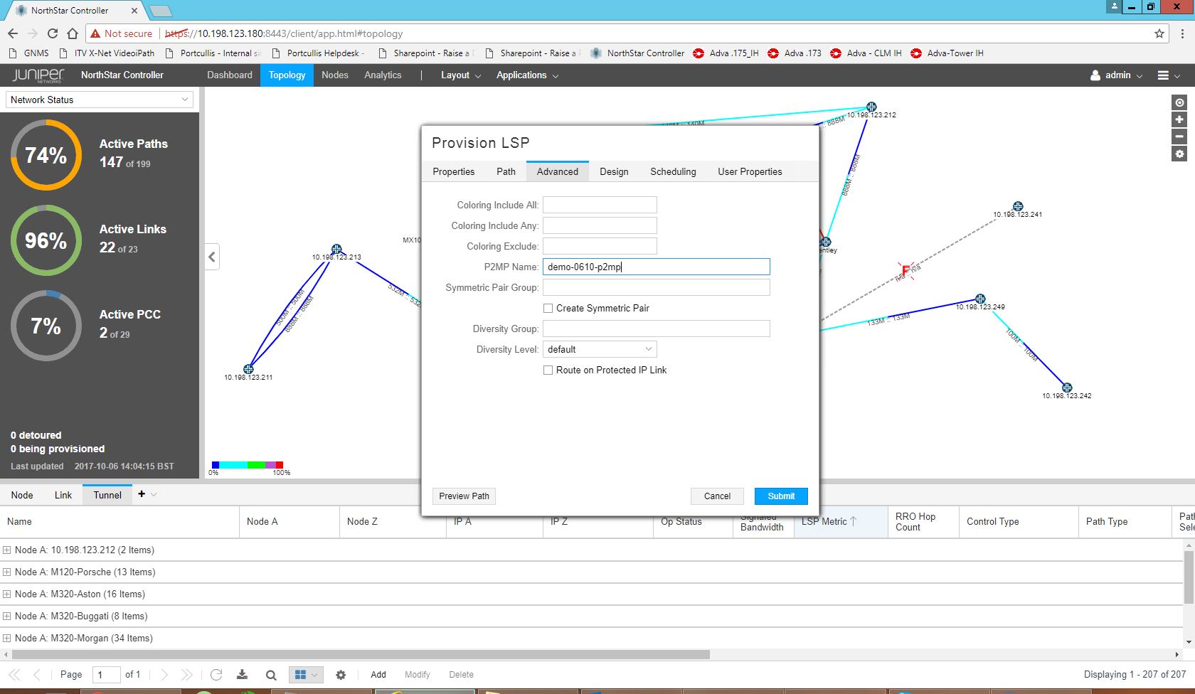
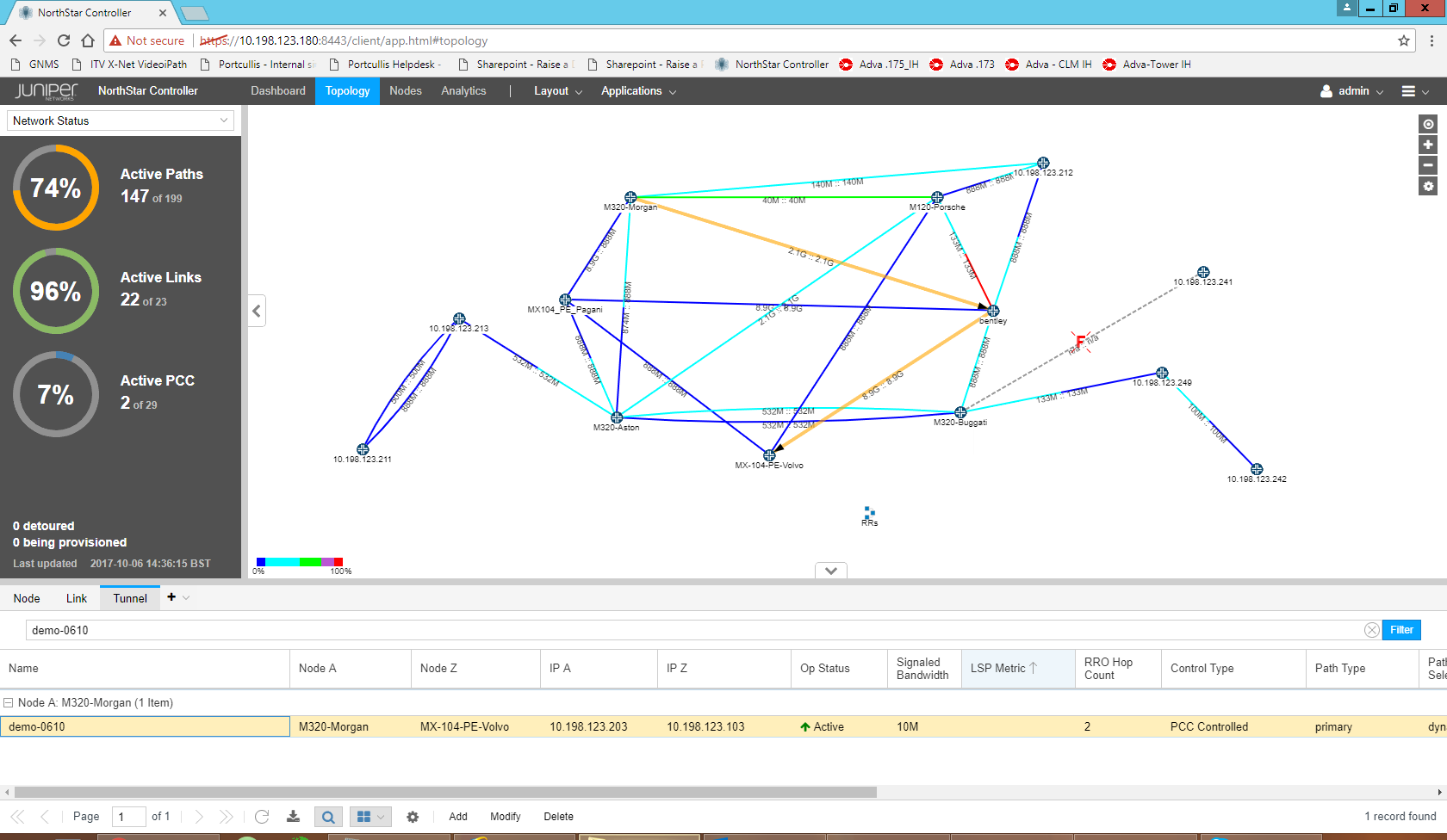
Let’s configure a sample L3VPN using this

See the snapshot which is basically a PUT request with XML payload
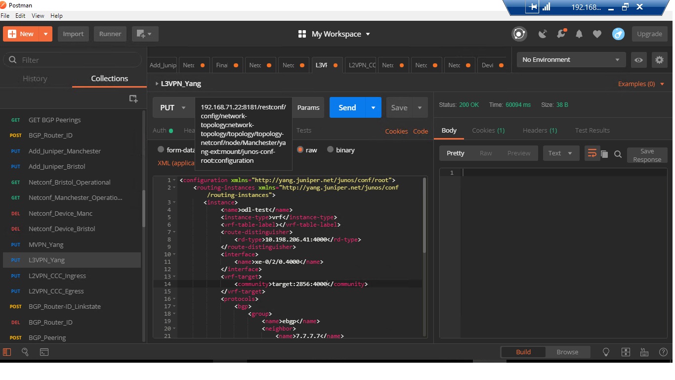
Send-L3VPN-Request

Lets’s verify

write@Manchester> show configuration routing-instances odl-test
instance-type vrf;
interface xe-0/2/0.4000;
route-distinguisher 10.198.206.41:4000;
vrf-target target:2856:4000;
vrf-table-label;
routing-options {
    multipath;
    protect core;
}
protocols {
    bgp {
        group ebgp {
            type external;
            peer-as 65101;
            as-override;
            neighbor 7.7.7.7 {
                authentication-key "$9$CuyoAORhclMLNylJDkP3nylKvWx"; ## SECRET-DATA
                bfd-liveness-detection {
                    minimum-interval 100;
                    multiplier 3;
                }
            }
        }
    }
}


Here you go.. its working 🙂

That’s all for today.. I will do a separate blog for other service configurations via ODL. Let me know if you have any questions.


Bbye

Mohit

Segment Routed L2VPN TE – Cisco IOS-XR

Hi All

Let’s see Segment routing in action in this blog particularly on IOS-XR. Segment routing is quite new concept which is picking pace these days. In my earlier blog I listed the differences between Segment routing and RSVP-TE and SR can replace it and there are certain areas where it may not be able to help however L3VPN and L2VPN Traffic Engineering is surely one area where it can be used and in this blog we will use SR as TE while configuring the L2VPN.

For this we will take NCS5508 as our router platform in below topology where we will configure the L2VPN SR-TE between NCS5508-1 to NCS5508-3 via NCS5508-8.

Segment Routing in IOS-XR


Let’s see the SR config first.

SR beauty is that there is no special protocol needed to run it. SR Labels will be advertised in OSPF/ISIS and these protocols have been uplifted to carry them. SR Labels are carried in Type 10 Opaque area LSA as TLV.

If you are familiar with OSPF config in IOS-XR, most of the config below looks similar to you as we have just enabled OSPF under area0 and added interfaces under it.

However there are 3 configs highlighted in RED which we have enabled for Segment routing.

RP/0/RP0/CPU0:ncs5508-1#show running-config router ospf
router ospf 1
 nsr
 distribute link-state
 segment-routing mpls
 nsf ietf
 segment-routing sr-prefer
 area 0
 mpls traffic-eng
 interface Loopback0
 passive enable
 prefix-sid index 1 explicit-null
 !
 interface HundredGigE0/1/0/0
 cost 1
 network point-to-point
 !
 interface FortyGigE0/2/0/8
 cost 4
 network point-to-point
 !
 interface FortyGigE0/2/0/10
 cost 4
 network point-to-point
 !
 interface FortyGigE0/2/0/18
 cost 4
 network point-to-point
 !
 !
 mpls traffic-eng router-id Loopback0
!

segment-routing mpls , this command causes OSPF to originate RI LSA, Extended Prefix and Extended Link LSAs. It enables MPLS on all interfaces in area(s) enabled for SR and programs SR MPLS labels for forwarding.

segment-routing sr-prefer is used to set the preference of segment routing (SR) labels over label distribution protocol (LDP) labels in case both are available towards destination in your network.

prefix-sid index 1 explicit-null — A prefix SID is associated with an IP prefix. The prefix SID is manually configured from the segment routing global block (SRGB) range of labels. The prefix segment steers the traffic along the shortest path to its destination. A node SID is a special type of prefix SID that identifies a specific node. It is configured under the loopback interface with the loopback address of the node as the prefix. The prefix SID is globally unique within the segment routing domain.

Let’s verify it

RP/0/RP0/CPU0:ncs5508-1#show ospf sid-database
SID Database for ospf 1 with ID 192.168.0.1

SID Prefix/Mask
-------- ------------------
1 192.168.0.1/32 (L)
2 192.168.0.2/32
3 192.168.0.3/32
4 192.168.0.4/32
5 192.168.0.5/32
6 192.168.0.6/32
7 192.168.0.7/32
8 192.168.0.8/32


In the same way we have configured the Node-SID as same index as last octet on lo0 interface.

RP/0/RP0/CPU0:ncs5508-1#show ospf database opaque-area 192.168.0.1/32
 OSPF Router with ID (192.168.0.1) (Process ID 1)
Type-10 Opaque Link Area Link States (Area 0)
LS age: 782
 Options: (No TOS-capability, DC)
 LS Type: Opaque Area Link
 Link State ID: 7.0.0.1
 Opaque Type: 7
 Opaque ID: 1
 Advertising Router: 192.168.0.1
 LS Seq Number: 800006fa
 Checksum: 0xed8b
 Length: 44
Extended Prefix TLV: Length: 20
 Route-type: 1
 AF : 0
 Flags : 0x40
 Prefix : 192.168.0.1/32
SID sub-TLV: Length: 8
 Flags : 0x50
 MTID : 0
 Algo : 0
 SID Index : 1
RP/0/RP0/CPU0:ncs5508-1#show mpls forwarding
Local  Outgoing    Prefix             Outgoing     Next Hop        Bytes
Label  Label       or ID              Interface                    Switched

—— ———– —————— ———— ————— ————

16002  Exp-Null-v4 SR Pfx (idx 2)     Hu0/1/0/0    50.50.50.30     0
16003  16003       SR Pfx (idx 3)     Hu0/1/0/0    50.50.50.30     0
16004  Exp-Null-v4 SR Pfx (idx 4)     Fo0/2/0/8    50.50.50.25     0
16005  16005       SR Pfx (idx 5)     Fo0/2/0/8    50.50.50.25     6421133
16006  16006       SR Pfx (idx 6)     Hu0/1/0/0    50.50.50.30     0
       16006       SR Pfx (idx 6)     Fo0/2/0/8    50.50.50.25     0
16007  16007       SR Pfx (idx 7)     Hu0/1/0/0    50.50.50.30     0
16008  Exp-Null-v4 SR Pfx (idx 8)     Fo0/2/0/18   50.50.50.38     0

Now let’s create a Segment routed TE EVPN based P2P L2 Circuit. 🙂

Ideally we know that Controller is needed to play with Segment routed labels and Controller can insert the appropriate labels required for TE however if you don’t have Controller, you can configure the path by explicitly giving the path through which traffic will be going.

So we will start with l2vpn xconnect taking edge interface on NCS5508-1 and assigning a EVPN EVI 1100 with source and target ac-id (attachment circuit id) and associate it with pw-class which we will define in next step.


RP/0/RP0/CPU0:ncs5508-1#show running-config l2vpn xconnect group evpn-vpws p2p vpws1
l2vpn
 xconnect group evpn-vpws
 p2p vpws1
 interface HundredGigE0/2/0/2.1100
 neighbor evpn evi 1100 target 11003 source 11001
 pw-class vpws1-class
 !
 !
 !
! 

Pw-class is associated with sr-te policy to steer traffic through the network. An SR-TE policy path is expressed as a list of segments that specifies the path, called a segment ID (SID) list. Each segment is an end-to-end path from the source to the destination, and instructs the routers in the network to follow the specified path instead of the shortest path calculated by the IGP

RP/0/RP0/CPU0:ncs5508-1#show running-config l2vpn pw-class vpws1-class
l2vpn
 pw-class vpws1-class
 encapsulation mpls
 preferred-path sr-te policy vpws1-policy
 !
 !
!
RP/0/RP0/CPU0:ncs5508-1#show running-config segment-routing traffic-eng policy vpws1-policy
segment-routing
 traffic-eng
 policy vpws1-policy
 color 10 end-point ipv4 192.168.0.3
 candidate-paths
 preference 200
 dynamic
 metric
 type te
 !
 !
 !
 preference 300
 explicit segment-list vpws1-path
 !
 !
 !
 !
 !
!

So in our policy, we have defined one preferred path which is dynamic and if that fails it should failover to explicitly configured segment list defined via path vpws1-path.

RP/0/RP0/CPU0:ncs5508-1#show running-config segment-routing traffic-eng segment-list vpws1-path
segment-routing
 traffic-eng
 segment-list vpws1-path
 index 10 address ipv4 50.50.50.38
 index 20 address ipv4 50.50.50.21
 !
 !
!

So if we see currently the route towards NCS5508-3, it’s going via IGP Route and not taking our defined list which is expected.

RP/0/RP0/CPU0:ncs5508-1#show route 192.168.0.3
Wed Jun 27 14:49:59.487 UTC
Routing entry for 192.168.0.3/32
 Known via "ospf 1", distance 110, metric 3, labeled SR, type intra area
 Installed Jun 27 14:47:18.930 for 00:02:40
 Routing Descriptor Blocks
 50.50.50.30, from 192.168.0.3, via HundredGigE0/1/0/0
 Route metric is 3
 No advertising protos.

So let’s see our L2VPN status.

RP/0/RP0/CPU0:ncs5508-1#show l2vpn xconnect group evpn-vpws detail
Group evpn-vpws, XC vpws1, state is up; Interworking none
 AC: HundredGigE0/2/0/2.1100, state is up
 Type VLAN; Num Ranges: 1
 Rewrite Tags: []
 VLAN ranges: [1100, 1100]
 MTU 9016; XC ID 0x1000001; interworking none
 Statistics:
 packets: received 157064234, sent 157063216
 bytes: received 234968088320, sent 234966565392
 drops: illegal VLAN 0, illegal length 0
 EVPN: neighbor 192.168.0.3, PW ID: evi 1100, ac-id 11003, state is up ( established )
 XC ID 0xc0000001
 Encapsulation MPLS
 Source address 192.168.0.1
 Encap type Ethernet, control word disabled
 Sequencing not set
 Preferred path Active : SR TE vpws1-policy, Statically configured, fallback enabled
 Tunnel : Up

 EVPN  Local Remote
 ------------ ------------------------------ -----------------------------
 Label 64007 64006
 MTU   9016  9016
 Control word disabled disabled
 AC ID 11001 11003
 EVPN type Ethernet Ethernet

So if we go n shut the primary dynamic path we can see the forwarding table moves over to our segment-list defined for label 16003 which is for NCS5508-3.

RP/0/RP0/CPU0:ncs5508-1#config t
Wed Jun 27 14:58:04.096 UTC
RP/0/RP0/CPU0:ncs5508-1(config)#int HundredGigE0/1/0/0
RP/0/RP0/CPU0:ncs5508-1(config-if)#shutdown
RP/0/RP0/CPU0:ncs5508-1(config-if)#commit
RP/0/RP0/CPU0:ncs5508-1#show mpls forwarding
Local Outgoing Prefix Outgoing Next Hop Bytes
Label Label or ID Interface Switched
------ ----------- ------------------ ------------ --------------- ------------
16002 16002 SR Pfx (idx 2) Fo0/2/0/18 50.50.50.38 0
16003 16003 SR Pfx (idx 3) Fo0/2/0/18 50.50.50.38 0


So thats all, i hope you like the blog and let me know your feedback.


Regards

Mohit


PCEP Initiated LSP using OpenDayLight and Juniper vMX

Hi All

In this post, we will look at Open day light controller working with Juniper vMXs and how we can use the controller to get the BGP, BGP-LS and PCEP working. Once everything is up and running we will use the Controller to initiate the PCEP initiated MPLS LSPs between 2 VMXs.

Sounds interesting? Let’s see how we can achieve this.

Before I go further, if you want to check anything on PCEP and some of its concept, I did a post on Juniper Northstar Controller some time ago which you can check.

https://networkzblogger.com/2017/03/17/juniper-northstar-wan-sdn-controller/

Below is the topology we will be using where all Juniper VMXs are loaded in Virtual Control Plane mode and they have fxp0 interface in 192.168.71.x subnet. Open day light controller version is Nitrogen and we have booted it on CentOS 7.5 version.

There is Windows VM in same subnet also from where we will run the REST APIs calls to Open day light using POSTMAN App.

Topology Diagram
Topology Diagram


We will divide the post into 3 parts.

  • Configuring BGP/BGP-Link state between ODL and 192.168.71.24 VMX-3.
  • Configuring PCEP session between all VMXs and ODL
  • Initiate MPLS LSP from ODL using PCEP

I am assuming that you already know how to start an ODL controller. However if you don’t know let me know and I can help you.

So lets start with 1) Configuring BGP/BGP-Link state between ODL and 192.168.71.24 VMX-3.

If you already don’t know, Open day light versions in recent times doesn’t come auto-installed with all the features. You have to manually add them. You don’t need to download them individually. It’s just you need to activate them.

We will be configure the BGP and BGP-LS on VMX-3 first

Standard BGP config with IPv4 Unicast address family however for BGP-LS we have to enable a separate family traffic-engineering additionally.

root@VMX-3> show configuration protocols bgp
group opendaylight {
 type internal;
 description Controller;
 local-address 192.168.71.24;
 family inet {
 unicast;
 }
 family traffic-engineering {
 unicast;
 }
 peer-as 2856;
 neighbor 192.168.71.22;
}

On ODL side, First install the BGP and restconf feature on karaf console using command

feature:install odl-restconf odl-bgpcep-bgp

Then using REST API we will enable the BGP Router-ID with Link State family

POST URL : 192.168.71.22:8181/restconf/config/openconfig-network-instance:network-instances/network-instance/global-bgp/openconfig-network-instance:protocols

POST Request_BGP Router ID

Then Configure the peer 192.168.71.24 with specific BGP Parameters and families

POST URL: 192.168.71.22:8181/restconf/config/openconfig-network-instance:network-instances/network-instance/global-bgp/openconfig-network-instance:protocols/protocol/openconfig-policy-types:BGP/bgp-test-odl/bgp/neighbors

POST Request_BGP Peer

We can check the status of BGP peering off course from VMX side but let’s see what comes up from ODL side

GET URL: 192.168.71.22:8181/restconf/operational/bgp-rib:bgp-rib/rib/bgp-test-odl/peer/bgp:%2F%2F3.3.3.3

GET Request_BGP Peering

From VMX side:

root@VMX-3> show bgp neighbor
Peer: 192.168.71.22+27755 AS 2856 Local: 192.168.71.24+179 AS 2856
 Description: Controller
 Group: opendaylight Routing-Instance: master
 Forwarding routing-instance: master
 Type: Internal State: Established Flags: <Sync>
 Last State: OpenConfirm Last Event: RecvKeepAlive
 Last Error: None
 Options: <Preference LocalAddress LogUpDown AddressFamily PeerAS Refresh>
 Options: <VpnApplyExport DropPathAttributes>
 Address families configured: inet-unicast te-unicast
 Path-attributes dropped: 128
 Local Address: 192.168.71.24 Holdtime: 90 Preference: 170
 Number of flaps: 2
 Last flap event: RecvNotify
 Error: 'Cease' Sent: 0 Recv: 33
 Peer ID: 192.168.71.22 Local ID: 3.3.3.3 Active Holdtime: 90
 Keepalive Interval: 30 Group index: 0 Peer index: 0 SNMP index: 0
 I/O Session Thread: bgpio-0 State: Enabled
 BFD: disabled, down
 NLRI for restart configured on peer: inet-unicast te-unicast


BGP-LS configuration we did will be used to advertise the Traffic Engineering database to Controller. You can see the routes advertised using lsdist.0 table in juniper.

Snippet below:

root@VMX-3> show route table lsdist.0
lsdist.0: 11 destinations, 11 routes (11 active, 0 holddown, 0 hidden)
+ = Active Route, - = Last Active, * = Both
NODE { AS:2856 Area:0.0.0.0 IPv4:2.2.2.2 OSPF:0 }/1152
 *[OSPF/10] 02:02:38
 Fictitious
NODE { AS:2856 Area:0.0.0.0 IPv4:3.3.3.3 OSPF:0 }/1152
 *[OSPF/10] 02:02:43
 Fictitious
NODE { AS:2856 Area:0.0.0.0 IPv4:4.4.4.4 OSPF:0 }/1152
 *[OSPF/10] 02:02:38
 Fictitious
NODE { AS:2856 Area:0.0.0.0 IPv4:4.4.4.4-192.168.71.26 OSPF:0 }/1152
 *[OSPF/10] 02:02:31
 Fictitious
LINK { Local { AS:2856 Area:0.0.0.0 IPv4:2.2.2.2 }.{ IPv4:192.168.71.23 } Remote { AS:2856 Area:0.0.0.0 IPv4:4.4.4.4-192.168.71.26 }.{ } OSPF:0 }/1152
 *[OSPF/10] 02:02:31
 Fictitious
..
…
…


2) Now let’s configure the PCEP

On VMX (This will be repeated on all with change in local address)

root@VMX-3> show configuration protocols pcep
pce odl {
 local-address 192.168.71.24;
 destination-ipv4-address 192.168.71.22;
 destination-port 4189;
 pce-type active stateful;
 lsp-provisioning;
 p2mp-lsp-report-capability;
}

If you have any firewall, make sure to allow port 4189 between Controller and VMXs.

On ODL, we need to install odl-bgpcep-pcep feature

There is no other config to do. As soon as you install this feature, you should see PCEP status up.

Let’s see it from VMX-4


root@VMX-4> show path-computation-client status
Session Type            Provisioning Status
odl     Stateful Active On           Up

LSP Summary
 Total number of LSPs : 0
 Static LSPs : 0
 Externally controlled LSPs : 0
 Externally provisioned LSPs : 0/16000 (current/limit)
 Orphaned LSPs : 0

odl (main)
 Delegated : 0
 Externally provisioned : 0

From ODL side:

GET Request_PCEP Status

3)      PCEP Initiated LSP

Now, we will configure the LSP from VMX-3 to VMX-4 between their Loopback IPs.

POST URL: 192.168.71.22:8181/restconf/operations/network-topology-pcep:add-lsp

You can see we haven’t given any ERO while provisioning the LSP. ODL has auto calculated the path and you can verify in VMX-3

PCEP LSP ADD with No Ero
root@VMX-3> show mpls lsp name test-pcep-2 extensive
Ingress LSP: 1 sessions

4.4.4.4
 From: 3.3.3.3, State: Up, ActiveRoute: 0, LSPname: test-pcep-2
 ActivePath: (primary)
 LSPtype: Externally provisioned, Penultimate hop popping
 LSP Control Status: Externally controlled
 LoadBalance: Random
 Encoding type: Packet, Switching type: Packet, GPID: IPv4
 LSP Self-ping Status : Enabled
 *Primary State: Up, Preference: 200
 Priorities: 0 0
 External Path CSPF Status: external
 SmartOptimizeTimer: 180
 Flap Count: 0
 MBB Count: 0
 Received RRO (ProtectionFlag 1=Available 2=InUse 4=B/W 8=Node 10=SoftPreempt 20=Node-ID):
 192.168.71.26(Label=0)
 12 May 24 12:10:08.334 Self-ping ended successfully
 11 May 24 12:10:07.830 EXTCTRL LSP: Sent Path computation request and LSP status
 10 May 24 12:10:07.830 EXTCTRL_LSP: Computation request/lsp status contains: signalled bw 0 req BW 0 admin group(exclude 0 include any 0 include all 0) priority setup 0 hold 0
 9 May 24 12:10:07.829 Selected as active path
 8 May 24 12:10:07.828 EXTCTRL LSP: Sent Path computation request and LSP status
 7 May 24 12:10:07.828 EXTCTRL_LSP: Computation request/lsp status contains: signalled bw 0 req BW 0 admin group(exclude 0 include any 0 include all 0) priority setup 0 hold 0
 6 May 24 12:10:07.828 Up
 5 May 24 12:10:07.828 Self-ping started
 4 May 24 12:10:07.828 Self-ping enqueued
 3 May 24 12:10:07.828 Record Route: 192.168.71.26(Label=0)
 2 May 24 12:10:07.824 Originate Call
 1 May 24 12:10:07.824 EXTCTRL_LSP: Received setup parameters ::
 Created: Thu May 24 12:10:07 2018
Total 1 displayed, Up 1, Down 0


You can do various operations like Deleting LSP, Modifying LSP etc from REST API.

One thing which we can’t do at the moment using PCEP is configuring Point to Multipoint LSP as standard is still being drafted for this but I hope it will come out soon.

So that’s all for now, I hope you enjoyed it and let me know your feedback.


Regards

Mohit


Segment Routing v/s RSVP-TE?

SR (Segment Routing) is new and trending topic these days in Telecom Networks. It’s promising and some vendors are pushing for it because of the way we can leverage SDN Controller to steer the traffic through the Network plus how it will remove need of LDP/RSVPE-TE from core however i think there are still some of the use cases where it lacks some capabilities currently. I hope in future all these areas will be fixed and SR becomes THE Option of choice for all Service Providers. These are all my opinions and it would be good to know your views on it.

1)      Bandwidth Reservation issue –> Using SR we can’t reserve the bandwidth in our Network for each LSP as we can do with RSVP-TE. Bandwidth reservation can be critical in some Service provider/Broadcast networks to provide the customer with dedicated bandwidth. We can argue that Controller at the Top can look at the whole Network and would be able to easily manage the reservations however Controller is a single point of failure and I don’t think we can depend upon Controller for this crucial behaviour.?

2)      Lack of Multicast P2MP Support –> Multicast proposes more challenge for the segment routing. SR can only replace Point to point LDP/RSVP-TE however some of the Telecom Networks uses P2MP Multicast services as part of NG-MVPN and for those we still need to depend on RSVP-TE . Moreover MPLS-based multicast solutions have matured now after many years’ of development. I think keeping 2 Technologies i.e one for P2P L2/L3VPN and other for P2MP MVPN will add complexity only to network.

3)      Depth of MPLS Label Stack –> We know that forwarding packets need to push a SR header with a list of segments(labels). Now there are 2 main types of SR Labels. One is Node and other is Adjacency (link). To provide granularity to route the traffic via 15-20 hops we need to push more Adjacency labels at Ingress PE accordingly. This depth of label stack may be a challenge for some type of devices.

Plz see some of the labels stack present in hardware:  (Courtesy: NANOG.org)

Linux (kernel 4.10): 2-3 SID’s

Low end off the shelf (merchant) silicon, e.g. BCM Trident2: 3-5 SID’s

High end off the shelf (merchant) silicon, e.g BCM Jericho1 : 4-7 SID’s

Vendor’ silicon, e.g. Juniper’ Trio: 4-10+ SID’s

Even though Vendor may be able to support 15-20 Label stack, we can end up in payload efficiency and MTU issues i.e. because of big size of the header will reduce the efficiency of payload.

4)      State Issues –> One major advantage for segment routing proposed was that the State is only maintained at the head-end. No state is maintained at mid-points and tail-ends. This is good in case if we have Node and Adjacency/Link labels only however there are proposals for Prefix segment Labels also which will increase the state on all the points in network and I don’t think behaviour will be different from LDP/RSVP-TE then.

In case of centrally controlled environment where Controller will take care of everything it will be difficult for Operations Teams to troubleshoot in case anything goes wrong in Network as they need to know the architecture of each device whether it is capable of getting around the Label stack issue via that device. We may be thinking of putting low end devices near to Customer edge as PEs and high end in middle of core, however due to label stack issue we may need to put high end routers only everywhere.

I am not against SR however i would be really pleased if these issues can be taken care or already available (i may well be living in old times) however from my perspective, there is scalability issue which limits application scenarios for segment routing. It may be better for cases where service provider is mostly providing  unicast L2/L3VPN services.

Let me know your views on this and how you are using SR in your environment 🙂


JunOS Automation using PyEZ and Northstar REST APIs

Hi All, in this session lets discuss some Automation.

During past few days, I was looking at some REST APIs for Juniper Northstar Controller. Now Northstar is good for LSP creation/deletion/modification but it cant configure the service E2E. Offcourse that tool is not meant to do all this but Juniper has recently released one beta version of it which can bind your LSP to some service which is excellent step forward. We will see that in a moment. Juniper is leveraging Jinja templates in NS to achieve this binding.

However as I said still service creation is not E2E and for that I thought of adding one more layer of automation and for this I have used Juniper own PyEZ framework which is basically Juniper Python library for automating tasks. Brilliant lets see how this work.

Juniper PyEZ is a framework which is easily grasped by Network engineers and you don’t need to be programmer to fully understand it.

https://www.juniper.net/documentation/en_US/junos-pyez/topics/concept/junos-pyez-overview.html

REST (REpresentational State Transfer) is a set of useful conventions and principals about transfer of information over the World Wide Web.

Many Web services are now using the principals of REST in their design.

When you type a URL into your browser, like http://example.net, your browser software creates an HTTP header that identifies:

  • a desired action: GET (“get me this resource”).
  • a target machine (www.domain-name.com).

The NorthStar RESTful APIs are designed to enable access over HTTP to most of the same data and analytics that are available to you from both the NorthStar GUI and the NorthStar CLI.

https://www.juniper.net/documentation/en_US/northstar3.1.0/information-products/api-ref/api-ref.html

Below is the pictorial representation of what we will be doing. I have used a Windows server on which we will write a script which will talk to Northstar using REST APIs and other components of Juniper Pes using PyEZ.

L2VPN CCC
Automation Model


Our Script will be written in Python and you can write the variables value in excel and pass it to the script.

Our excel format:

L2VPN_CCC_Data

import httplib
import json
import time
import re
import sys
import pandas as pd
from jnpr.junos import Device
from jnpr.junos.utils.config import Config
from pprint import pprint

df = pd.read_excel("L2VPN_CCC_Data.xlsx","Sheet1")

PE1 = str((df['PE1'].values.tolist())[0])
PE2 = str((df['PE2'].values.tolist())[0])
Interface_PE1 = str((df['Interface_PE1'].values.tolist())[0])
Unit_PE1 = str((df['Unit_PE1'].values.tolist())[0])
Vlan_PE1 = str((df['Vlan_PE1'].values.tolist())[0])
Interface_PE2 = str((df['Interface_PE2'].values.tolist())[0])
Unit_PE2 = str((df['Unit_PE2'].values.tolist())[0])
Vlan_PE2 = str((df['Vlan_PE2'].values.tolist())[0])
LSP_Name_PE1 = str((df['LSP_Name_PE1'].values.tolist())[0])
LSP_Name_PE2 = str((df['LSP_Name_PE2'].values.tolist())[0])
VPN_CCC_PE1 = str((df['VPN_CCC_PE1'].values.tolist())[0])
VPN_CCC_PE2 = str((df['VPN_CCC_PE2'].values.tolist())[0])

dev1 = Device(host=''+PE1+'', user='demo', password='password', port='22')
dev1.open()
dev1.timeout = 300

with Config(dev1, mode='private') as cu: 
cu.load('set interfaces '+Interface_PE1+' unit '+Unit_PE1+' description L2VPN-CCC encapsulation vlan-ccc vlan-id '+Vlan_PE1+' family ccc', format='set')
cu.pdiff() #Printing the difference in the configuration after the load
cu.commit()

dev1.close()
dev2 = Device(host=''+PE2+'', user='demo', password='password', port='22')
dev2.open()
dev2.timeout = 300

with Config(dev2, mode='private') as cu: 
cu.load('set interfaces '+Interface_PE2+' unit '+Unit_PE2+' description L2VPN-CCC encapsulation vlan-ccc vlan-id '+Vlan_PE2+' family ccc', format='set')
cu.pdiff() #Printing the difference in the configuration after the load#
cu.commit() #commit#

dev2.close()
conn = httplib.HTTPConnection('10.198.123.180:8091')
Bandwidth = raw_input('Please enter LSP Bandwidth on '+PE1+' (e.g 100k): ')
Setup_Pri = raw_input('Please enter Set up Priority: ')
Hold_Pri = raw_input('Please enter Hold Priority: ')
payload = str('{\r\n\"name\": \"'+LSP_Name_PE1+'\",\r\n\"creationConfigurationMethod\": \"NETCONF\",\r\n\"provisioningType\": \"RSVP\",\r\n  \"pathType\": \"primary\",\r\n  \"from\": {\r\n\"topoObjectType\": \"ipv4\",\r\n\"address\": \"'+PE1+'\"\r\n },\r\n  \"to\": {\r\n\"topoObjectType\": \"ipv4\",\r\n\"address\": \"'+PE2+'\"\r\n},\r\n\"plannedProperties\": {\r\n\"bandwidth\": \"'+Bandwidth+'\",\r\n\"setupPriority\": '+Setup_Pri+',\r\n\"holdingPriority\": '+Hold_Pri+',\r\n\"userProperties\": {\r\n \"ccc-vpn-name\": \"'+VPN_CCC_PE1+'\",\r\n \"ccc-interface\": \"'+Interface_PE1+'.'+Unit_PE1+'\",\r\n\"transmit-lsp\": \"'+LSP_Name_PE1+'\",\r\n\"receive-lsp\": \"'+LSP_Name_PE2+'\"\r\n    }\r\n  }\r\n}\r\n')
headers = {
 'content-type': "application/json",
'cache-control': "no-cache",
 }

conn.request ("POST", "/NorthStar/API/v2/tenant/1/topology/1/te-lsps", payload, headers
res = conn.getresponse()
data = res.read()
print 'Please wait while we get the status of LSP you created :)'
for i in xrange(25,0,-1):
 time.sleep(1)
 sys.stdout.write(str(i)+' ') 
 sys.stdout.flush()
 conn.request("GET", str('/NorthStar/API/v2/tenant/1/topology/1/te-lsps/search?name=' + LSP_Name_PE1), headers=headers
 res = conn.getresponse()
 data = res.read()

LSP_Status = re.search('operationalStatus":(.*?),', data).group(1)
if LSP_Status == '"Active"':
  print ('\nSuccess: LSP "'+LSP_Name_PE1+'" is Created and Active')
elif LSP_Status == "Down":
   print ('\nFailed: LSP "'+LSP_Name_PE1+'" is created however Down')
else:
  print ('\nFailed: LSP "'+LSP_Name_PE1+'" is not created and is in Unknown State on Northstar')

time.sleep(10)

conn = httplib.HTTPConnection('10.198.123.180:8091')
Bandwidth = raw_input('Please enter LSP Bandwidth on '+PE2+' (e.g 100k): ')
Setup_Pri = raw_input('Please enter Set up Priority: ')
Hold_Pri = raw_input('Please enter Hold Priority: ')

payload = str('{\r\n\"name\": \"'+LSP_Name_PE2+'\",\r\n\"creationConfigurationMethod\": \"NETCONF\",\r\n\"provisioningType\": \"RSVP\",\r\n  \"pathType\": \"primary\",\r\n  \"from\": {\r\n\"topoObjectType\": \"ipv4\",\r\n\"address\": \"'+PE2+'\"\r\n },\r\n  \"to\": {\r\n\"topoObjectType\": \"ipv4\",\r\n\"address\": \"'+PE1+'\"\r\n},\r\n\"plannedProperties\": {\r\n\"bandwidth\": \"'+Bandwidth+'\",\r\n\"setupPriority\": '+Setup_Pri+',\r\n\"holdingPriority\": '+Hold_Pri+',\r\n\"userProperties\": {\r\n \"ccc-vpn-name\": \"'+VPN_CCC_PE2+'\",\r\n \"ccc-interface\":\"'+Interface_PE2+'.'+Unit_PE2+'\",\r\n\"transmit-lsp\": \"'+LSP_Name_PE2+'\",\r\n\"receive-lsp\": \"'+LSP_Name_PE1+'\"\r\n    }\r\n  }\r\n}\r\n')
headers = {
 'content-type': "application/json",
 'cache-control': "no-cache",
   }

conn.request ("POST", "/NorthStar/API/v2/tenant/1/topology/1/te-lsps", payload, headers)
res = conn.getresponse()
data = res.read()
print 'Please wait while we get the status of LSP you created :)'
for i in xrange(25,0,-1):
   time.sleep(1)
   sys.stdout.write(str(i)+' ')
   sys.stdout.flush()

conn.request("GET", str('/NorthStar/API/v2/tenant/1/topology/1/te-lsps/search?name=' + LSP_Name_PE2), headers=headers)
res = conn.getresponse()
data = res.read()
LSP_Status = re.search('operationalStatus":(.*?),', data).group(1)
if LSP_Status == '"Active"':
    print ('\nSuccess: LSP "'+LSP_Name_PE2+'" is Created and Active')
elif LSP_Status == "Down":
    print ('\nFailed: LSP "'+LSP_Name_PE2+'" is created however Down')
else:
    print ('\nFailed: LSP "'+LSP_Name_PE2+'" is not created and is in Unknown State on Northstar')

time.sleep(5)

dev1.open()
dev2.open()

print (dev1.cli('show connections remote-interface-switch '+VPN_CCC_PE1+'', warning=False))

print (dev2.cli('show connections remote-interface-switch '+VPN_CCC_PE2+'', warning=False))

dev1.close()
dev2.close()

In this script we are making reading the values from the excel and using it as variables in or script.

After that using PyEZ, making a SSH connection to PE1 and PE2 and configuring the layer 2 sub-interfaces with vpn-ccc encapsulations. Once that is done, connection to Northstar server 10.198.123.180 using httplib libraris/modules is made and waiting for Northstar to configure the LSP. At this stage Northstar is also binding that LSPs in connections using Jinja template. Once Northstar has created the LSPs we are using regular expression to get the LSP Index from Northstar and checking whether LSP creating in Success or failed.

At last we are printing the show command output to find out if everything is up and running 🙂

Lets see by running the script

C:\Program Files (x86)\Python\Northstar_Scripts\Working\Juniper\L2VPN_CCC>python
 E2E_L2VPN_CCC_Script.py
[edit interfaces xe-2/0/0]
+ unit 601 {
+ description L2VPN-CCC;
+ encapsulation vlan-ccc;
+ vlan-id 601;
+ family ccc;
+ }
[edit interfaces xe-2/0/0]
+ unit 601 {
+ description L2VPN-CCC;
+ encapsulation vlan-ccc;
+ vlan-id 601;
+ family ccc;
+ }
Please enter LSP Bandwidth on 10.198.123.100 (e.g 100k): 70m
Please enter Set up Priority: 5
Please enter Hold Priority: 0
Please wait while we get the status of LSP you created :)
25 24 23 22 21 20 19 18 17 16 15 14 13 12 11 10 9 8 7 6 5 4 3 2 1
Success: LSP "l2vpn-ccc-1" is created and is Active
Please enter LSP Bandwidth on 10.198.123.205 (e.g 100k): 70m
Please enter Set up Priority: 5
Please enter Hold Priority: 0
Please wait while we get the status of LSP you created :)
25 24 23 22 21 20 19 18 17 16 15 14 13 12 11 10 9 8 7 6 5 4 3 2 1
Success: LSP "l2vpn-ccc-2" is created and is Active
CCC and TCC connections [Link Monitoring On]
Legend for status (St): Legend for connection types:
 UN -- uninitialized if-sw: interface switching
 NP -- not present rmt-if: remote interface switching
 WE -- wrong encapsulation lsp-sw: LSP switching
 DS -- disabled tx-p2mp-sw: transmit P2MP switching
 Dn -- down rx-p2mp-sw: receive P2MP switching
 -> -- only outbound conn is up Legend for circuit types:
 <- -- only inbound conn is up intf -- interface
 Up -- operational oif -- outgoing interface
 RmtDn -- remote CCC down tlsp -- transmit LSP
 Restart -- restarting rlsp -- receive LSP
Connection/Circuit Type St Time last up # Up tran
s
l2vpn-ccc rmt-if Up Nov 25 12:52:10
1
 xe-2/0/0.601 intf Up
 l2vpn-ccc-1 tlsp Up
 l2vpn-ccc-2 rlsp Up

CCC and TCC connections [Link Monitoring On]
Legend for status (St): Legend for connection types:
 UN -- uninitialized if-sw: interface switching
 NP -- not present rmt-if: remote interface switching
 WE -- wrong encapsulation lsp-sw: LSP switching
 DS -- disabled tx-p2mp-sw: transmit P2MP switching
 Dn -- down rx-p2mp-sw: receive P2MP switching
 -> -- only outbound conn is up Legend for circuit types:
 <- -- only inbound conn is up intf -- interface
 Up -- operational oif -- outgoing interface
 RmtDn -- remote CCC down tlsp -- transmit LSP
 Restart -- restarting rlsp -- receive LSP

Connection/Circuit Type St Time last up # Up tran
s
l2vpn-ccc rmt-if Up Nov 25 12:52:11
1
 xe-2/0/0.601 intf Up
 l2vpn-ccc-2 tlsp Up
 l2vpn-ccc-1 rlsp Up

C:\Program Files (x86)\Python\Northstar_Scripts\Working\Juniper\L2VPN_CCC>


So that’s all for today.. You can see the possibility of using this framework in so many tasks in your daily networking journey. I hope you like this blog and will try to use it in your network 🙂

Regards

Mohit

Juniper Northstar SDN Controller – Part 2

Following on my earlier blog on Northstar here: https://networkzblogger.com/2017/03/17/juniper-northstar-wan-sdn-controller, recently I got chance to work on next release of it which has among other things is ability to initiate P2MP (Point to Multipoint) LSPs. P2MPs are big use case in Media and Broadcast network and ability to create them via controller would be too helpful. However there is a catch. As discussed in my earlier blog, the NorthStar (NS) Controller relies on PCEP (Path Computation Element Protocol) to deploy a path between the PCC router and PCE (Controller). Currently P2MPs are not initiated by PCEP or its standard is not ratified. So Juniper have come up with another way of configuring it and that’s via Netconf. NETCONF provides mechanisms to install, manipulate, and delete the configuration of network devices. Its operations are realized on top of a simple Remote Procedure Call (RPC) layer. The protocol messages are exchanged on top of a secure transport protocol like SSH etc.

In this blog, instead of looking at PCEP based LSPs from Northstar we will explore netconf functionality and what other features have been introduced in new ns version.

Below is our current model which is built using TED (Traffic Engineering Database) by Northstar and if you look closely there are 2 devices which have PCEP session up because they have correct Junos code on it (15.1F6 and later) however all others are having netconf session Up even if they are on Junos 10, 12, 14 etc. which is cool thing. So as long as you have netconf stanza added in Junos config and have ssh connectivity that is all Northstar need to connect to devices.

Pic-1

Lets start by configuring a P2MP LSP via Northstar

You can see 2 options here for provisioning method. One is PCEP and other is Netconf.

Pic-2

We will choose Netconf and fill other bits.

Pic-3

We have kept Path as dynamic however we can choose required path to TE it more. Under Advanced Tab, you will see P2MP Name field, in which we have added the P2MP name.

Pic-4

All others field you can pretty much keep default.

Once you submit it, Northstar will open a netconf session on port 830 towards headend router which is M320 in our case and push and commit the config to it.

Pic-5

You can see above LSP has become Active and its showing the path as well which this LSP is taking. Now one of the biggest difference between PCEP created LSP and one created from Netconf is that Netconf LSPs will be part of startup-config in Junos as the configs are committing to it so it can be slow process getting your LSP up based upon commit time. Also all Netconf created LSPs are basically shown as PCC Controlled. However PCEP just sent LSP state to network to build E2E path rather than config. PCEP LSP config still resides in NS database and LSPs are created within seconds and are PCE Initiated.

M320> show configuration protocols mpls label-switched-path demo-0610
from 10.198.123.203;
to 10.198.123.103;
p2mp demo-0610-p2p;
primary demo-0610.p0 {
 apply-groups demo-0610-p2p;
}

M320> show configuration groups demo-0610-p2p
protocols {
 mpls {
 label-switched-path <*> {
 primary <*> {
 bandwidth 10m;
 priority 7 7;
 }
 }
 }
}

Ok so that’s for P2MP LSPs which is clean. In 3.1.0 one of the issue we found was related to commit process. Suppose you have 10 LSPs to be created from one source to destination. With Netconf, NS will commit 10 times individually for those LSPs which can be time consuming on some of the MX104s, MX80s with less CPU power. Juniper is looking to change this and putting the commit in batches to decrease the overall time and commit process which would be excellent J

So we have seen now how P2MP LSPs are created via Netconf however we haven’t seen how Netconf parameters are configured on NS as with netconf you can see the analytics data as well which is populated by Telemetry. We will see Telemetry in some other blog.

Under Administration -> Device Profiles we have to set the parameters for individual device.

Pic-6

We enable Netconf and add login details and password. You can test the connectivity as well from NS before actually trying to provision the network.

Pic-7

Apart from P2MP, another thing which has been introduced is while provisioning the LSP you can select which routing method you need to choose. There are many methods starting from default to routebyPCC, etc. default means that NS will calculate the path and routebyPCC means routers will calculate the path and NS won’t be having any say in it.

Pic-8

Another new feature which has been introduced in release 3.1.0 is setting the current path as explicit.

So above P2MP LSP I created was just dynamic however if we want to explicitly make this path as Strict so that LSP doesn’t change path based upon the network conditions we can configure it as below.

Pic-9

If we see the CLI now, NS has filled strict path in it.

M320> show configuration protocols mpls path demo-0610.p0
10.177.177.5 strict;
10.0.0.245 strict;

Ok that’s all for this blog. I hope you like it and let me know your views if you are looking at using NS for your network and if you are already, what are your use cases J


R

Mohit Mittal